
 OCSKAYMARK/ISTOCK/GETTY IMAGES PLUS
Digital Workflow and Fully Guided Surgery for Immediate Implants
An exploration of using digital techniques and fully guided surgery for a patient who received extractions, residual ridge reduction, and immediately placed and loaded dental implants.
Edentulism affects a patient’s well being and quality of life, including nutritional disturbance.1 Dentistry has come a long way since Branemark’s titanium root form dental implants were introduced in the 1960s.2 Depending upon the complexity of the case, implant-supported restorative treatment is usually a multistep process requiring hard and/or soft tissue augmentation procedures, implant placement surgery, and restoration. However, there are graftless solutions with decreased treatment time for edentulous patients that have shown to significantly improve their quality of life.3,4 When the patient’s anatomy and inter-arch space are favorable, the choice of restoration for complete edentulism is generally either an implant-supported overdenture or a fixed, detachable hybrid restoration.5 Studies that assessed fixed detachable prostheses by placing four to six implants between the mental foramina report a high success rate.4–6 When inter-arch space is not favorable, ridge reduction is required to achieve adequate dimension for the prosthesis. However, the issue of rehabilitation of the lost vertical dimension also needs to be addressed. There are many advantages when an implant-supported prosthesis is combined with an immediate implant loading protocol, including (but not limited to) reduced treatment time, fewer postoperative visits, elimination of the second stage surgery, cost efficiency, and avoiding a removable prosthesis during the healing phase.1 This approach also improves patient satisfaction, self-perception, function and esthetic results.7,8
Cone beam computed tomography (CBCT) has become an indispensable diagnostic and treatment planning tool due to its wide-ranging applications. The utility of a three-dimensional (3D) view of the anatomical structures, coupled with faster image acquisition and lower radiation exposure, has made CBCT popular. Although it provides high accuracy in spatial resolution, it seems to be inadequate for soft tissue evaluation due to limited contrast resolution.9 The assessment of gingival tissue is generally difficult due to interference from the tongue and lips, and therefore requires a special technique during image acquisition.10 Low-contrast application is preferred when soft tissue interpretation is needed, although the effect of artifacts from radiation scatter may be more noticeable.9
Dental therapies utilizing digital intraoral scanners are also becoming popular. Fixed dental prostheses — such as crowns and bridges — fabricated using intraoral scanners and computer aided design/computer aided manufacturing (CAD/CAM) technology have greater accuracy and reliability when compared to appliances made using conventional elastomeric impression materials. However, the use of intraoral scanners over soft tissue is still a concern due to tissue mobility and reflection from saliva.11 Therefore, it is sometimes necessary to make definitive casts by using conventional elastomeric impression materials when intraoral scanners cannot provide satisfactory results.
The use of CBCT, digital scanners and CAD/CAM has revolutionized implant dentistry and allowed patients to have all their teeth extracted and leave with new functional prostheses the same day. The virtual implant planning process using the aforementioned technologies allows for placing the implants in the desired positions in real time on a computer.12 These technologies also allow for custom-built bone reduction and implant placement templates that can aid the fabrication of a provisional restoration and immediate loading protocol ahead of the actual surgery.13
The following clinical report demonstrates the digital workflow using CBCT imaging, combined with virtual treatment planning involving 3D model scanning and CAD/CAM technology for implant placement. This case also utilized fully guided, bone-borne bone reduction and implant placement templates for an immediately restored, full-arch fixed prosthesis in the mandible.
CASE PRESENTATION
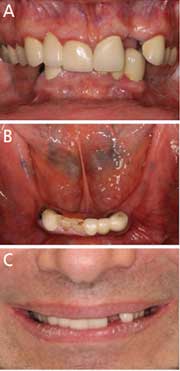
A healthy 55-year-old male with partially edentulous dentition presented for implant restoration of his missing maxillary and mandibular teeth. The patient was diagnosed with plaque-induced gingivitis and partial edentulism, along with vertical and horizontal ridge deficiency in the maxillary and mandibular posterior areas. Intraoral examination revealed deep bite occlusion, subgingival caries on the lower canines, and clinical crown defects with secondary caries on the right central and lateral incisors. Hence, all the mandibular teeth were deemed hopeless (Figures 1A through 1C). The patient wanted a fixed interim prosthesis inserted immediately after implant placement. The treatment plan included extraction of all remaining mandibular teeth, followed by immediate implant placement at sites #20, 22, 24, 27 and 29, with immediate interim prosthesis insertion. Five implants were planned in case one or more implants would not be favorable for immediate loading after placement. The patient gave his informed consent prior to his inclusion in this report.
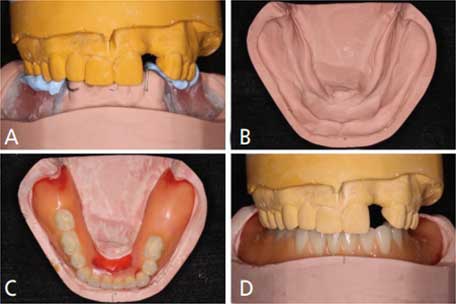
Intraoral, extraoral and radiographic evaluations confirmed a stable maxillomandibular relationship, including the expectation that a stable increased occlusal vertical dimension was necessary. A record base and occlusal rim were utilized to verify the desired maxillomandibular relationship so the rehabilitation space could be achieved (Figures 2A through 2D). Anterior ridge reduction was deemed necessary due to bilateral ridge resorption and inadequate interocclusal clearance for the fixed prosthesis since the restorative space was less than the recommended 12 to 15 mm from soft tissue to opposing dentition.14
Owing to the complex nature of the treatment plan, a digital implant planning workflow for a fully guided surgical protocol was used. The patient’s final impression of the mandibular arch would be used for immediate fixed denture fabrication. A duplication of the mandibular definitive cast was made using polyvinyl siloxane, and both casts were split mounted in the same position as the patient’s centric relation. Tentative mandibular ridge reduction was performed on one of the definitive casts to acquire the adequate interocclusal clearance (Figure 2B), followed by denture teeth setup and wax-up based on the space available for immediate prosthesis fabrication (Figures 2C and 2D). Cone beam imaging was performed to acquire the preoperative anatomic information. The Digital Imaging and Communications in Medicine (DICOM) files generated from the CBCT, along with both mandibular casts (a preoperative definitive cast and tentative ground cast with wax-up), were sent to the lab.
Prior to initiating digital planning, three 3D model scans were performed: the preoperative definitive cast, tentative ground cast without wax-up, and the tentative ground cast with wax-up. The DICOM files from the CBCT and the three scans were imported to implant planning software. All DICOM files were superimposed to render the final image for surgical planning. The procedure of superimposition was as follows: the preoperative definitive cast DICOM file was first superimposed with the radiographic DICOM file by using three arbitrary reference points on the hard tissue (teeth). Next, the DICOM file of the tentative ground cast without wax-up was imported by using three arbitrary reference points on the same location of both casts (Figures 3A through 3D). The last DICOM file was subsequently merged in the same manner.
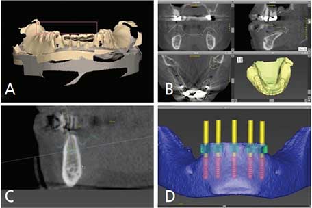
This process established a clear soft tissue outline that could be viewed from the axial, coronal and sagittal planes (Figure 3B). The thickness of this established soft tissue served as a reference for implant platform selection (Figure 3C). The interocclusal relationship and vertical dimension were verified prior to digital surgical planning. Based on the virtual dental casts and DICOM data, the implant positions were planned for the mandibular interforaminal area (Figure 3D). Simulated bone reduction was finalized from the tentative ground cast in the virtual implant planning software to ensure adequate restorative space for the future mandibular interim and final prostheses. Based on a prosthetically driven protocol, virtual implant placement was performed in the software in an anatomically and restoratively appropriate position.
Upon finalizing the implant positions, two surgical guides — bone-borne bone reduction and implant placement templates (Figures 4A and 4B) — were designed and fabricated using CAD/CAM technology. The bone reduction template was designed to be fitted on the alveolar ridge on both sides by extending the flanges distally to improve stability. The window created over the extraction sockets served as a vertical bone reduction reference plane. The implant placement template possessed two identical distally extended flanges to provide initial stability during implant placement. The base fit of the implant placement template could also be used to verify adequate reduction of the anterior ridge.
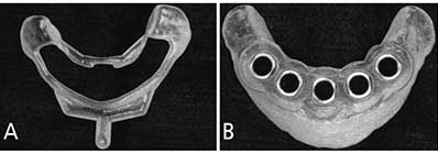
reference plane (A). Implant placement template (B).
TREATMENT
On the day of surgery, all of the remaining mandibular teeth were extracted under local anesthesia and a full thickness mucoperiosteal flap was reflected to accommodate the bone reduction template (Figures 5A through 5C). The alveolar crest was reduced until the bone level was flush with the window of the bone reduction template. The second implant placement template was subsequently seated on the reduced ridge to provide guidance for osteotomy preparation. Osteotomies were performed using the guided surgical template, following the manufacturer’s protocol. The initial osteotomy was started at the most distal sites #29 and 20. The surgical drill sequence was initiated with a 2.2-mm drill, followed by a 2.8-mm drill, which was used to final depth of 10 mm. The implant placement template was stabilized using 2.8-mm fixation pins at sites #29 and 20 (Figure 5B).
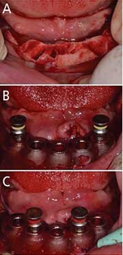
template in place (A). At sites #29 and 20, 2.8-mm drills were used to a final depth of 10 mm; next, the
implant placement template was stabilized using 2.8-mm fixation pins at sites #29 and
20 (B). A 3.5-mm osteotomy preparation was finished at sites of #22, 24 and 27, and
the implant placement
template was stabilized
by placing 3.5-mm fixation pins at sites #22 and 27 (C).
All surgical drills and fixation pins were color coded according to their sizes in order to avoid confusion during the surgical procedure. The implant drilling sequence was followed at sites #22, 24 and 27 until the final depth of 10 mm. Next, the drilling sequence at sites #29 and 20 was completed to the final size while the guide continued to be stabilized by replacing the 2.8-mm fixation pins with 3.5-mm fixation pins at sites #22 and 27 (Figure 5C). Five tissue-level implants were placed in the planned positions. Tissue-level implants were used since this was a one-stage surgery, and because they allow better soft tissue management and crestal bone preservation. After implant placement, all remaining jumping distance15 within the sockets were grafted with xenograft bone particulate.
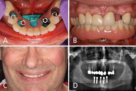
Five healing abutments were temporarily placed under a torque of 15 Ncm and the flaps were approximated with 4-0 resorbable synthetic suture material without tension. At this point, the surgical site was ready for insertion of the immediate interim prosthesis. For implants to be immediately loaded, Roccuzzo et al14 suggested an insertion torque of 30 Ncm or greater for unitary implants, and 20 Ncm for multiple splinted implants. With primary stability measuring more than 35 Ncm for implants #20, 22, 27 and 29, an immediate loading protocol was followed. Implant #24 was not attached due to the insertion torque measuring less than 20 Ncm. Implant position was transferred to the interim prosthesis using bite registration material. The patient was guided to bite gently in centric relation during the transfer to secure the occlusal contact and vertical dimension. The access holes for intraoral pickup were created after all implant platform locations were identified. Four healing abutments were subsequently replaced by temporary abutments (Figures 6A through 6D).
The interim prosthesis was gently inserted and it was confirmed that no interference or unfavorable contact existed between the interim prosthesis, temporary abutments and opposing dentition. The interim prosthesis was picked up intraorally using self-curing attachment pickup resin. The occlusal contacts were adjusted and verified for even distribution in centric relation. Group function and elimination of premature contact were achieved in eccentric movement with multiple contacts between the maxillary teeth and mandibular interim prosthesis on the working side. The patient was given postoperative instructions, including a soft diet and use of 0.12% chlorhexidine gluconate mouthrinse postoperatively. The patient was satisfied with the outcome of the immediately inserted interim prosthesis (Figures 6B through 6D). He was dismissed with no postsurgical complications and scheduled for a one-week follow-up appointment. Postoperative follow-up was done for 12 weeks before the definitive impression appointment.
DISCUSSION
Even after ridge reduction, the present case had inadequate interarch space for a fixed detachable prosthesis, and therefore it was necessary to increase the patient’s vertical dimension. Loss of an intraoral reference point due to full mandibular arch extraction and ridge reduction, as well as the need for rehabilitation of lost vertical dimension, complicated treatment. Using a predetermined wax-up and provisional prosthesis provided an accurate maxillomandibular relationship and the desired vertical occlusion dimension. Therefore, full-skull CBCT imaging was not required (which also meant less radiation exposure for the patient, since only the mandibular arch was scanned).
The physically acquired maxillomandibular relationship and occlusal vertical dimension provided a reliable record for diagnosis, as reestablishment of vertical dimension was needed. The use of a record base and occlusal rim for diagnostic purposes, as well as to retain the accuracy of the maxillomandibular relationship, was necessary.8 The assessment of reestablished vertical dimension was easily performed and adjusted since physical perception was obtained directly from the patient. The evaluations of the muscular system, esthetic appearance, and phonetics were satisfactory for both the patient and clinician before the final maxillomandibular relationship record was determined.
The finalized maxillomandibular relationship record was transferred to the DICOM file from the tentative ground cast with wax-up, which provided the desired outline of the prosthesis. In turn, this facilitated the determination of bone reduction volume. Virtual implant planning was therefore performed digitally, and without the interference of scatter from the CBCT image. Due to the limitations of current technology and digital software, the condylar movements could not be precisely recorded. The design of the occlusal scheme and fabrication of the provisional restoration could only be arranged in the acquired centric occlusion position. Occlusal adjustment was done in laterotrusive movements to eliminate interference when the interim prosthesis was inserted. Further follow-up and occlusal adjustments were also required.
The use of CBCT could be restricted in this case due to the presence of multiple metallic fixed restorations. The radiation scatter from the metal can compromise its 3D volume rendering quality and, thus, assessment of soft tissue contours.16 Although sophisticated software tools are available to enhance the soft tissue outline and remove radiation scatter, it is a time-consuming process that involves a learning curve to operate the software efficiently and maintain accuracy.8 On the other hand, even with the precision of intraoral scanning on hard tissue, the reliability of soft tissue evaluation remains questionable due to tissue mobility and presence of saliva.11 The patient had many metallic substructure restorations in the mandibular teeth that caused severe scatter in the CBCT image, creating a challenge in treatment planning. This issue was addressed during the digital planning phase with the standard tessellation language (STL) or stereolithographic files generated from scanning the solid casts, which eliminated potential errors from radiation scatter and helped acquire a reliable outline of soft tissue due to the absence of saliva and tissue mobility.
A 3D assessment of soft tissue could then be easily performed and implant platform height could be predetermined based on the given soft tissue thickness. The clear and well-defined hard tissue outline from the merged STL files facilitated data mergence for imaging processing and subsequent diagnosis, treatment planning, and fabrication of the surgical templates.
SUMMARY
This report describes a digital workflow for a case requiring reestablishment of vertical dimension. It involved digital planning, full mandibular arch extraction, residual ridge reduction, guided immediate implant placement, and an immediately loaded interim prosthesis. Throughout therapy, the use of CBCT, 3D model scanning and CAD/CAM aided diagnosis, case planning and treatment.
KEY TAKEAWAYS
- When the patient’s anatomy and inter-arch space are favorable, the choice of restoration for complete edentulism is generally either an implant-supported overdenture or a fixed, detachable hybrid restoration.5
- There are many advantages when an implant-supported prosthesis is combined with an immediate loading protocol, including reduced treatment time, fewer postoperative visits, elimination of the second stage surgery, cost efficiency, and avoiding a removable prosthesis during the healing phase.1
- This approach also improves patient satisfaction, self-perception, function and esthetic results.7,8
- This clinical report describes a digital workflow for a patient whose treatment required reestablishment of vertical dimension.
- The case involved digital planning, full mandibular arch extraction, residual ridge reduction, fully guided immediate implant placement, and an immediately loaded interim prosthesis in the mandible.
REFERENCES
- Ciabattoni G, Acocell A, Sacco R. Immediately restored full-arch fixed prosthesis on implants placed in both healed and fresh extraction sockets after computer planned flapless guided surgery. A 3-year follow-up study. Clin Implant Dent Relat Res. 2017;19:997–908.
- Abraham CM. A brief historical perspective on dental implants, their surface coatings and treatments. Open Dent J. 2014;8:50–55.
- Kwon TH, Bain PA, Levin L. Systematic review of short- (5–10 years) and long-term (10 years or more) survival and success of full-arch fixed dental hybrid prostheses and supporting implantsJ J Dent. 2014;10:1228–1241.
- Turkyilmaz I, Company AM, McGlumphy EA. Should edentulous patients be constrained to removable complete dentures? The use of dental implants to improve the quality of life for edentulous patients. Gerodontology. 2010;27:3–10.
- Chee W, JivraJ S. Treatment planning of the edentulous mandible. Br Dent J. 2006;201:337–347.
- Rodriguez AM, Orenstein IH, Morris HF, Ochi S. Survival of various implant-supported prosthesis designs following 36 months of clinical function. Ann Periodontol. 2000;5:101–108.
- Dierens M, Collaert B, Deschepper E, Browaeys H, Klinge B, DeBruyn H. Patient-centered outcome of immediately loaded implants in the rehabilitation of fully edentulous jaws. Clin Oral Implants Res. 2009;20:1070–1077.
- Charette JR, Goldberg J, Harris BT, Morton D, Llop DR, Lin WS. Cone beam computed tomography imaging as a primary diagnostic tool for computer-guided surgery and CAD-CAM interim removable and fixed dental prostheses. J Prosthet Dent. 2016;116:157–165.
- Sarment D. Cone Beam Computed Tomography: Oral and Maxillofacial Diagnosis and Applications. Hoboken, NJ: Wiley-Blackwell; 2013:127–147.
- Januario AL, Barriviera M, Duarte WR. Soft tissue cone-beam computed tomography: a novel method for the measurement of gingival tissue and the dimensions of the dentogingival unit. J Esthet Restor Dent. 2008;20:366–373.
- Patzelt SB, Vonau S, Stampf S, Att W. Assessing the feasibility and accuracy of digitizing edentulous jaws. J Am Dent Assoc. 2013;144:914–920.
- Lin WS, Harris BT, Morton D. Use of CBCT imaging, open-source modeling software, and desktop stereolithography 3D printing to duplicate a removable dental prosthesis — a proof of concept. Compend Contin Educ Dent. 2017;38:5–8.
- Amorfini L, Storelli S, Romeo E. Rehabilitation of a dentate mandible requiring a full arch rehabilitation. Immediate loading of a fixed complete denture on 8 implants placed with a bone-supported surgical computer-planned guide: a case report. J Oral Implantol. 2011;37:106–113.
- Roccuzzo M, Aglietta M, Cordaro L. Implant loading protocols for partially edentulous maxillary posterior sites. Int J Oral Maxillofac Implants. 2009;24(Suppl):147–157.
- Botticelli D, Berglundh T, Buser D, Lindhe J. The jumping distance revisited: an experimental study in the dog. Clin Oral Impl Res. 2003;14:35–42.
- Mora MA, Chenin DL, Arce RM. Software tools and surgical guides in dental-implant-guided surgery. Dent Clin North Am. 2014;58:597–626.
The authors have no commercial conflicts of interest to disclose.
From Decisions in Dentistry. March 2021;7(3):16–18,21–22.
