
Blended Workflows in the Planning and Delivery of Dental Implants
Incorporating a blended workflow of digital and conventional techniques can improve outcomes in dental implant therapy.
Digital technology has streamlined many areas of dentistry. Surgical guides, for example, minimize local, patient and/or esthetic risk factors during implant surgery. More importantly, they outline treatment for the surgical and restorative team from its onset. Computer aided design and computer aided manufacturing (CAD/CAM) can then be used to fabricate implant abutments, single and multiunit prostheses, and frameworks using various techniques.
Even with the advantages and flexibility of digital approaches, conventional workflows still provide valuable information and feedback to troubleshoot errors in the planning and production stages. Proper implant placement, tissue management, and occlusal rehabilitation are key to long-term health and treatment success. Thus, incorporating a blended workflow of digital and conventional techniques will improve the predictability of implant dentistry, resulting in fewer complications.
The prosthetic setup of implant-supported restorations largely depends on accurate diagnostic information. In general, measurement errors using cone beam computed tomography (CBCT) are less than 0.5 mm.1 The resulting digital imaging and communication in medicine (or DICOM) file is then interpreted by planning software. It is worth noting that no statistically significant differences in implant transfer accuracy were found among three computer aided surgery systems on cadaver mandibles.2
A digital impression is then captured intraorally or extraorally on a model to create a stereolithography (.STL) file. It is merged with the DICOM file on an implant planning software to fabricate a guide. Each software comes programmed with different tooth shapes, virtual articulators and other resources to draft the proposed restoration.3 Conventional wax-ups can also be scanned and incorporated into the planning software for reference, especially in cases with difficult occlusal schemes or high esthetic demands. This can help convey any restorative or surgical challenges early on.
SURGICAL GUIDES AND WORKFLOWS
The surgical approach can vary based on the proposed guide. Tooth-borne guides are supported by the adjacent teeth and anatomy. A recent systematic review and meta-analysis found these guides had significantly fewer deviations in the implant angle, entry and apex points compared to mucosal- and bone-borne guides.4 Mucosal-borne guides are inherently less predictable because their retention is affected by the variability in soft tissue thickness. In fact, sites with thicker mucosa were associated with greater implant deviation.5 Bone-borne guides are mainly used in full-arch rehabilitation in the edentulous patient due to the invasive means required to fully seat them. They are limited by bone volume, shape and quality. Not surprisingly, a prospective study found increased pain intensity and related analgesic consumption with the intraoperative use of these guides.6
Different materials can be used to fabricate static guides. No significant differences were found in implant deviation or apical depth in guides prepared with three-dimensional printing or milling techniques.7 The dentist can also provide a conventional, nonrestrictive guide to the surgeon based on the wax-up. Caution is advised when freehand techniques are utilized, however, as they can prove less accurate than guided approaches, especially in inexperienced hands. For example, there were statistically significant differences in the implant angle deviation between thermoformed and CAD/CAM templates.8 The number and distribution of the remaining teeth can, however, affect implant deviation — with greater discrepancies in transfer accuracy for larger edentulous spans.9 Modifications can be made to any of these guides with buccal or lingual slots to improve access more posteriorly or in patients with limited opening. Fixed by mini screws and stabilization pins, stackable guides better secure mucosa- and bone-supported guides in edentulous areas and communicate the extent of alveoloplasty needed.
MANUFACTURING AND DELIVERY OF IMPLANT PROSTHESES
An accurate impression is the critical first step in the definitive phase. Intraoral scanners allow clinicians to evaluate their work in real-time. They improve the chairside experience and communication, and reduce the need for other materials. Scan bodies, often specific to each implant system, are used to relay the implant position to the virtual and analog definitive casts. Their exact impact in implant transfer accuracy is still being studied.10 Dental lab scanners, however, have been shown to be significantly more precise than intraoral scanners, regardless of the distance between scan bodies on study models.11 It is therefore important to consider the in-office limitations of emerging machinery and its effect on patient outcomes.
Next, CAM technology is used to fabricate implant abutments, restorations and frameworks using additive or subtractive techniques.12 Milling, for example, uses computer aided machinery to cut uniform blocks of titanium, chromium cobalt, polymethylmethacrylate or zirconia to the desired shape. Printing is an additive method that layers materials into three-dimensional objects. When using this approach, resins are preferred because of their flexibility and versatility to print models, provisionals, occlusal splints, implant guides and custom trays.13
Titanium and ceramic abutments can also be produced with CAM technology. A systematic review found that CAD/CAM abutments had 100% survival rates at the five-year follow-up. The authors noted these devices performed similarly to conventionally fabricated or stock abutments, and that “implant survival appears unaffected by fabrication technique.”14 A prospective study also showed they provide better marginal stability, with significantly less mucosal recession compared to various stock abutments.15
BLENDED APPROACH
A blend of digital and conventional components is particularly helpful when treating the edentulous patient. In the first appointment, the edentulous arch is scanned to design and print a custom tray, and the lip support is recorded in repose and full animation. The custom tray is intentionally kept shorter, so wax can be added as part of the analog impression. Border molding is performed, and a wash impression is taken with light-body material to capture all pertinent anatomy. A wax rim is fabricated for occlusal and jaw-relation records. The trays and wax rims are scanned separately and then while articulated by hand. A facial scan can be integrated at this step.
Next, the resulting .STL files are merged and aligned to design provisional or “try-in” dentures. These are printed from the same CAD/CAM technology and adjusted as appropriate, pending patient interests. The final denture is milled from a one-piece monolithic disc. These discs have special, shell-like geometry and color hues to aid in more realistic processing. And because patient files are stored electronically, prostheses can be remanufactured at any time.
Many elements of the above protocol can be adopted in the fabrication of implant-supported fixed or removable appliances. In fact, intraoral scanning with polymer scan bodies was significantly more accurate with full-arch implant impressions than polyether impressions taken with a splinted open-tray technique.16 There is still much variability in CAD/CAM hardware and software, especially as new programs, materials and implant systems come to market, so clinicians should interpret these findings cautiously.
CASE REPORT
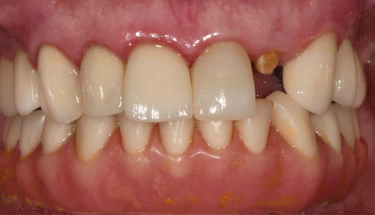
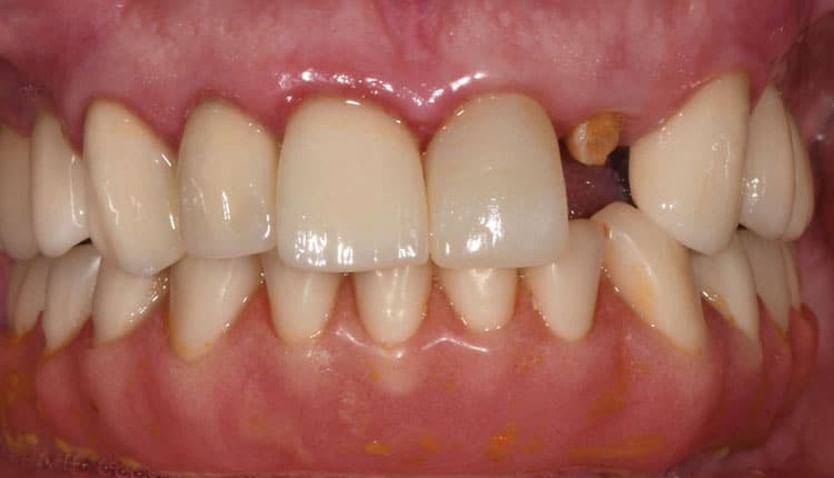
The following case illustrates the use of a blended workflow for implant placement in the anterior maxilla. A 78-year-old male presented to the graduate periodontics clinic at the University of Texas Health Science Center at San Antonio School of Dentistry interested in implant therapy to replace his failing crowns (Figures 1 through 15). His medical history was significant for diabetes, hypertension and angina, which were well-controlled with medications.
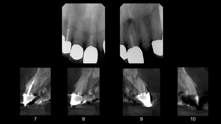
Due to the extent of caries noted after crown removal, compromised posts, and apical lesions noted on the CBCT scan, teeth #7 though 10 were deemed non-restorable. Immediate implant placement was not pursued due to patient finances and unfavorable ridge anatomy that would limit screw-channel access at the proposed implant sites. A comprehensive treatment plan was developed, and consents were obtained. Surgical procedures were performed using IV conscious sedation.
The treatment plan included:
- Extractions of teeth #7 to 10, with lateral ridge augmentation.
- Delayed implant placement at sites #8 and 9 using a printed surgical guide with custom healing abutments.
- Provisionalization of sites #8 and 9, with cantilevered pontics at sites #7 and 10.
- Definitive restorations for sites #8 and 9, with cantilevered pontics at sites #7 and 10.
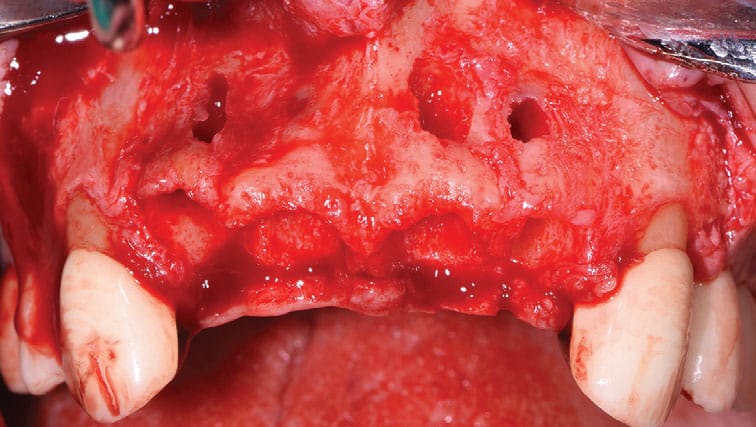
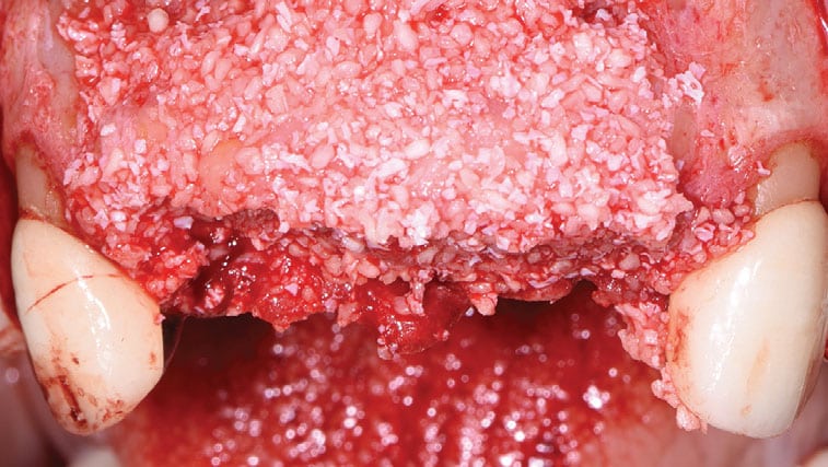
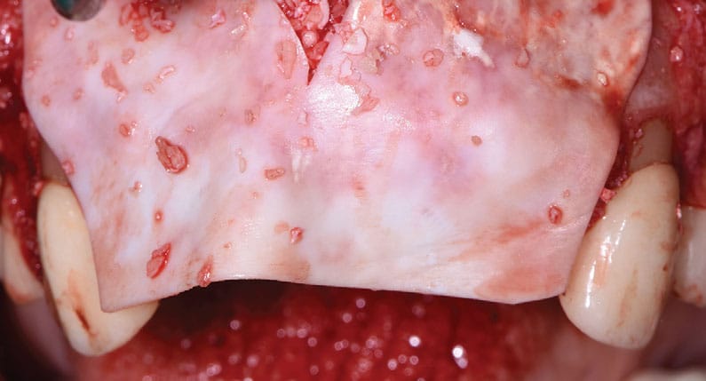
As part of the initial surgical procedure, buccal and palatal sulcular incisions were prepared from teeth #6 to 11 with distal vertical releases, and a full thickness flap was reflected. Teeth #7 to 10 were extracted in a minimally traumatic fashion, revealing multiple buccal fenestrations. Periosteal releasing incisions were prepared to allow for primary closure of the augmented sites. The deficient buccal plate at sites #7 to 10 was augmented with lateral onlay grafting using mineralized freeze-dried bone allograft. A resorbable membrane was layered over it. The goal was to correct the hard tissue deficiency prior to implant restoration.
The release needed for tension-free primary closure can result in coronal transposition of the alveolar mucosa, so patients should be forewarned of the need for possible soft tissue grafting when a limited zone of keratinized mucosa is present. Flaps were repositioned and secured using a combination of nonresorbable mattress and simple interrupted sutures. The restorative dentist delivered an Essix retainer to replace teeth #7 to 10, avoiding any tissue impingement.
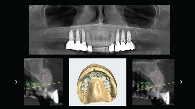
After six months, an intraoral scan was taken and then merged and aligned with CBCT imaging to design and print a surgical guide using planning software and an in-house printer. The decision was finalized to restore the edentulous span with two cantilevered pontics instead of an implant-supported bridge because of the guarded prognoses of teeth #6 and 11. Implants at sites #8 and 9 could be converted into one or two implant-supported bridges from teeth #6 to 11 when #6 and 11 are inevitably lost.
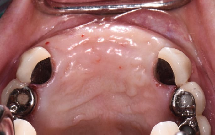
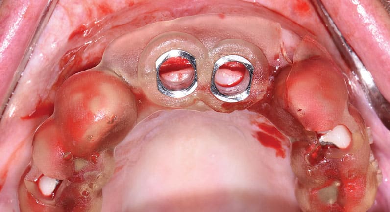
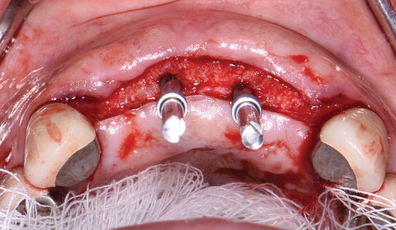
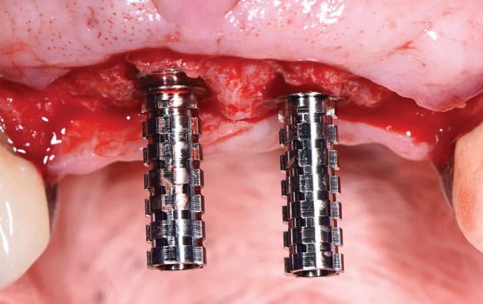
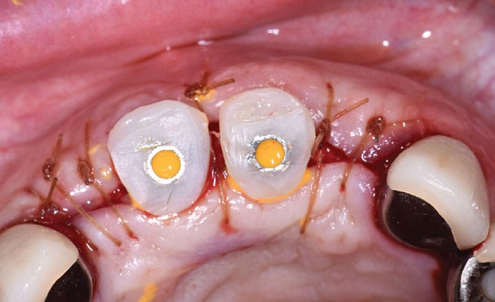
Buccal and palatal flaps were again prepared from teeth #6 to 11, and a full thickness flap was reflected. The printed guide was seated, and a surgical report was used throughout surgery to ensure proper implant positioning and placement. Two bone-level, 4.1-mm-wide and 12-mm-long implants were placed at sites #8 and 9 per the manufacturer’s recommendations, and primary stability was achieved. Custom healing abutments were fabricated chairside from a prefabricated jig of acrylic resin to develop the emergence profile from baseline. Flaps were secured with resorbable simple interrupted sutures.
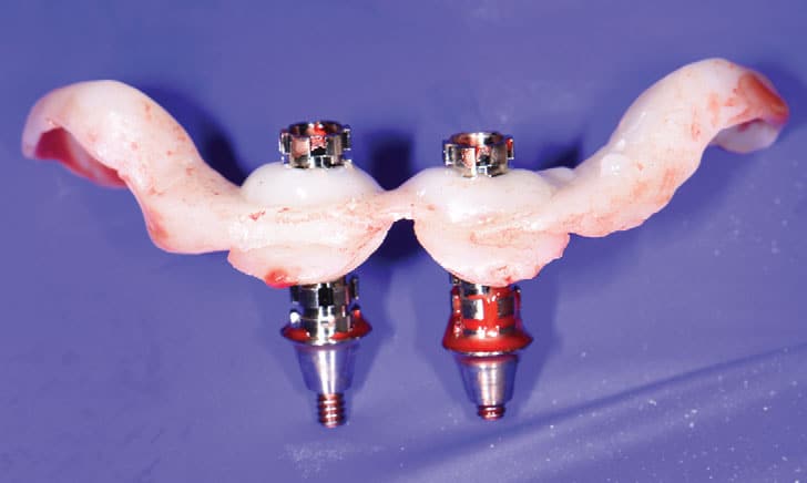
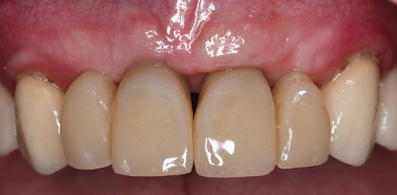
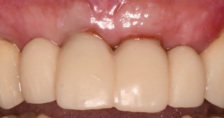
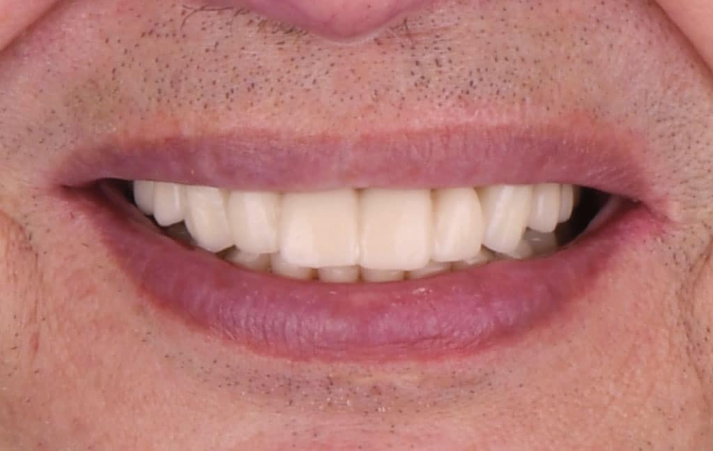
Postoperative instructions were reviewed. The patient returned for follow-up at two weeks and eight weeks. The tissues surrounding the implants were healthy, pink and firm, with no signs or symptoms of peri-implant disease. Analog and digital impressions were captured to mill several sets of polymethyl methacrylate implant provisionals and better control the soft tissue contours over the next few months. The patient returned to the clinic for fabrication of his final prostheses and will be seen for yearly recalls.
CONCLUSION
As with other digital techniques, CAD/CAM technology will continue to evolve and simplify implant dentistry. Guides, printers and milling units can facilitate different treatment scenarios to improve implant positioning and accuracy. However, clinicians should still be proficient in freehand implant placement and analog techniques because surgical complications and manufacturing errors can arise.
With proper training, implant providers can develop a strong foundation in surgical anatomy, soft tissue management and restorative dentistry. Taken together, integrating a blended workflow can improve the implant experience, resulting in fewer visits, less materials and reduced overall costs for patients and practitioners alike.
Acknowledgment: The author thanks Antonella A. Botto, DDS, for her prosthetic support in this case.
Key Takeaways
- While digital technology has streamlined many areas of dentistry, there are numerous instances — including dental implant therapy — where adopting a blended approach using conventional and digital techniques can improve the predictability of treatment.
- Even with the advantages and flexibility of digital approaches, conventional workflows still provide valuable information and feedback to troubleshoot errors in the implant planning and production stages.
- Conventional wax-ups can also be scanned and incorporated into the planning software for reference, especially in implant cases with difficult occlusal schemes or high esthetic demands. This can help convey any restorative or surgical challenges early on.
- Computer aided manufacturing technology can be used to fabricate implant abutments, restorations and frameworks using additive or subtractive techniques.12
- In fact, many elements of a blended protocol can be adopted in the fabrication of implant-supported fixed or removable prostheses.
- Taken together, integrating a blended digital and conventional workflow can result in fewer visits and reduced overall costs for patients and practitioners alike.
References
- Reddy MS, Mayfield‐Donahoo T, Vanderven FJ, Jeffcoat MK. A comparison of the diagnostic advantages of panoramic radiography and computed tomography scanning for placement of root form dental implants. Clin Oral Implants Res. 1994;5:229‐238.
- Ruppin J, Popovic A, Strauss M, Spuntrup E, Steiner A, Stoll C. Evaluation of the accuracy of three different computer-aided surgery systems in dental implantology: optical tracking vs. stereolithographic splint systems. Clin Oral Implants Res. 2008;19:709‐716.
- Flügge T, Derksen W, Te Poel J, Hassan B, Nelson K, Wismeijer D. Registration of cone beam computed tomography data and intraoral surface scans — a prerequisite for guided implant surgery with CAD/CAM drilling guides. Clin Oral Implants Res. 2017;28:1113‐1118.
- Raico Gallardo YN, da Silva-Olivio IR, Mukai E, Morimoto S, Sesma N, Cordaro L. Accuracy comparison of guided surgery for dental implants according to the tissue of support: a systematic review and meta-analysis. Clin Oral Implants Res. 2017;28:602–612.
- Vasak C, Watzak G, Gahleitner A, Strbac G, Schemper M, Zechner W. Computed tomography‐based evaluation of template (NobelGuide)‐guided implant positions: a prospective radiological study. Clin Oral Implants Res. 2011;22:1157‐1163.
- Arisan V, Karabuda CZ, Ozdemir T. Implant surgery using bone‐ and mucosa‐supported stereolithographic guides in totally edentulous jaws: surgical and post‐operative outcomes of computer‐aided vs. standard techniques. Clin Oral Implants Res. 2010;21:980‐988.
- Henprasert P, Dawson DV, El-Kerdani T, Song X, Couso-Queiruga E, Holloway JA. Comparison of the accuracy of implant position using surgical guides fabricated by additive and subtractive techniques. J Prosthodont. 2020;29:534–541.
- Matta RE, Bergauer B, Adler W, Wichmann M, Nickenig HJ. The impact of the fabrication method on the three‐dimensional accuracy of an implant surgery template. J Craniomaxillofac Surg. 2017;45:804‐808.
- Behneke A, Burwinkel M, Behneke N. Factors influencing transfer accuracy of cone beam CT-derived template-based implant placement. Clin Oral Implants Res. 2012;23:416–423.
- Mizumoto RM, Yilmaz B. Intraoral scan bodies in implant dentistry: A systematic review. J Prosthet Dent. 2018;120:343–352.
- Flügge TV, Att W, Metzger MC, Nelson K. Precision of dental implant digitization using intraoral scanners. Int J Prosthodont. 2016;29:277–283.
- Papaspyridakos P, Gallucci GO, Chen CJ, Hanssen S, Naert I, Vandenberghe B. Digital versus conventional implant impressions for edentulous patients: accuracy outcomes. Clin Oral Implants Res. 2016;27:465–472.
- Alghazzawi TF. Advancements in CAD/CAM technology: options for practical implementation. J Prosthodont Res. 2016;60:72–84.
- Kapos T, Evans C. CAD/CAM technology for implant abutments, crowns, and superstructures. Int J Oral Maxillofac Implants. 2014;29(Suppl):117–136.
- Lops D, Bressan E, Parpaiola A, Sbricoli L, Cecchinato D, Romeo E. Soft tissues stability of CAD/CAM and stock abutments in anterior regions: 2-year prospective multicentric cohort study. Clin Oral Implants Res. 2015;26:1436–1442.
- Amin S, Weber HP, Finkelman M, El Rafie K, Kudara Y, Papaspyridakos P. Digital vs. conventional full-arch implant impressions: a comparative study. Clin Oral Implants Res. 2017;28:1360–1367.
From Decisions in Dentistry. February 2023;9(2)8,10,13-14.
