

Maximizing Accuracy in Implant Planning and Surgical Execution
An overview of integrating DICOM, STL data, and surgical protocols for optimal implant outcomes.
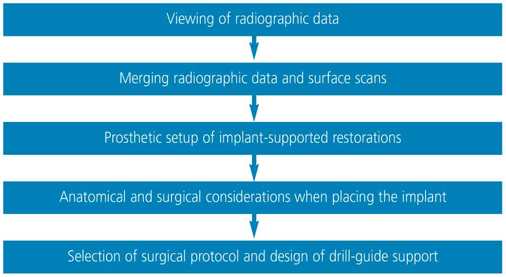
Once the Digital Imaging and Communications in Medicine (DICOM or .dcm) and Standard Tessellation Language (STL) data are acquired, implant planning software is utilized to plan the implant prosthesis and position. Although there may be some degree of variation in the order of the steps, the basic sequence is similar in all implant planning software. These steps are outlined in Figure 1.
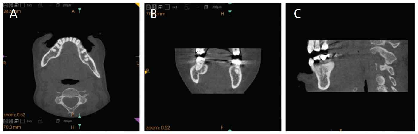
Viewing of radiographic data: As noted, three-dimensional (3D) volumetric data rendered from DICOM files are usually displayed as two-dimensional cross-sectional images: bucco-lingual (sagittal), anterior-posterior (axial), and mesiodistal (coronal; Figure 2). To better evaluate bone and dentinal structures for purposes of implant planning, these planes are segmented and a 3D model of bone and teeth is displayed (Figure 3).1

Merging radiographic data and surface scans: Because a 3D volumetric model reconstructed by segmentation of the cone-beam computed tomography (CBCT) data do not usually display teeth or soft tissue accurately, STL data derived from optical scans are merged with the 3D reconstructed model. Preferably, teeth surfaces on both data sets are used for merging. In cases in which a significant amount of scatter is present due to radiopaque materials in the dentition, clinicians can fabricate custom and standardized fiducial markers on a radiographic template, and these markers can be used as reference points to register multiple datasets.2 With these markers, CBCT scans need to be taken twice: with the patient wearing the radiographic template, and the template on its own. Both DICOM data sets are used in the merging process with the STL data. When tooth surfaces are used, only one CBCT scan is necessary. Merging should be done as accurately as possible since implant position will be planned based on the merged data. Any discrepancy in merging data sets will result in poor virtual implant planning and therefore improper implant positioning during surgical execution.3
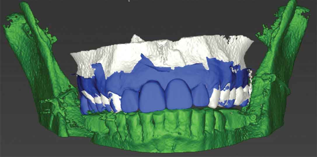
Prosthetic setup of implant-supported restorations: Once the DICOM and STL data are merged, the implant-supported restoration is designed prior to implant placement to ensure a prosthetically driven implant position. The diagnostic setup can also be used for the final implant restoration. Many computer-aided design (CAD) programs are available to design the prosthesis. Some software will provide standard teeth shapes, additional shaping tools, and virtual articulators to facilitate accurate and efficient tooth setup. A conventional wax-up can also be made on a stone model and scanned extraorally before being incorporated in the implant planning software as an additional STL file to merge with the data sets (Figure 4). Whether teeth are designed with CAD software or a conventional wax-up will not affect the final outcome. However, additional time may be needed to do an extraoral scan and transfer the conventional wax-up stone model into a virtual model.
Anatomical and surgical considerations when placing an implant: Clinicians attempting to surgically place implants should have thorough knowledge of vital anatomical structures they may encounter during placement to avoid complications during surgery.4 When planning an implant virtually, clinicians must ensure that a minimum of 1.5 mm of bone is present buccal to the planned implant in order to achieve optimal esthetics and peri-implant soft tissue stability. In cases in which buccal bone is expected to be less than 1.5 mm, clinicians should consider performing a guided bone regeneration procedure to avoid future tissue recession, which could compromise peri-implant soft tissue esthetics.5 When an implant is planned adjacent to another implant, a 3 mm mesiodistal distance is needed between both implants.6 In terms of depth, the implant should be placed fully in bone and 3 to 4 mm apical to the planned prosthesis margin if it was bone level, or 1 to 2 mm apical from the planned prosthesis margin if it was a tissue-level design.7
Selection of surgical protocol and design of drill-guide support: Once implant position is determined, the surgical template is designed. Surgical templates are supported by three kinds of tissue: bone, mucosa or tooth.8 Whenever possible, clinicians are advised to use a tooth-supported template due to its superior accuracy.9 Additionally, it is recommended to use more than two adjacent teeth as support for the template, as this will increase stability.10 The use of bone-supported templates is slightly more invasive, since a mucoperiosteal flap must be reflected to expose the underlying bone, which, in turn, results in increased postoperative discomfort and possible bone loss due to decreased blood supply.11 In comparison, mucosa-supported templates are less invasive and can reduce postoperative pain, discomfort, surgical time and healing time.12 However, the limitations include their dependence on mucosal thickness and resilience.13 Additionally, clinicians can utilize the templates for the initial pilot drill or perform the procedure fully guided. Usually, fully guided protocols are recommended due to the higher accuracy of implant placement.14
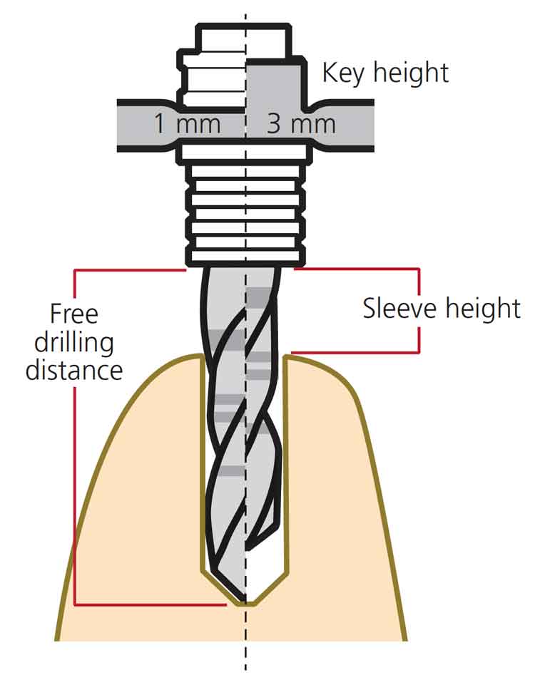
Drill guidance and deviation play a crucial role in the accuracy and outcome of static computer assisted implant surgeries (sCAIS). Deviations were thought to be due to either one or a combination of factors: sleeve height, drilling distance or guided key height. These choices differ in various implant systems and are made either by the clinician or generated by the implant planning software. It has been shown that accuracy of sCAIS is directly related to the free drilling distance apical to the guided sleeve and inversely related to the guided key height used above the sleeve (Figure 5). Therefore, when clinically possible, a protocol involving a shorter drill, lower sleeve height and longer drill key may have more favorable outcomes on the accuracy of sCAIS.15
Additionally, some deviations can occur after osteotomy and during implant placement. This could be due to inaccuracies of the drill or use of different implant macro designs, or both. It has been found that tapered implant macro designs have statistically significant higher positional accuracy when compared to parallel implant macro designs. This can be attributed to the design of the drill, thread, or insertion geometry.16
References
- Kernen FF. Pre-operative analysis and treatment planning in digital implant dentistry. Forum Implantologicum. 2019;15:8.
- Katsoulis J, Pazera P, Mericske-Stern R. Prosthetically driven, computer-guided implant planning for the edentulous maxilla: a model study. Clin Implant Dent Relat Res. 2009;11:238–245.
- Flügge T, Derksen W, Te Poel J, et al. Registration of cone beam computed tomography data and intraoral surface scans — a prerequisite for guided implant surgery with CAD/CAM drilling guides. Clin Oral Implants Res.2017;28:1113–1118.
- Greenstein G, Cavallaro J, Tarnow D. Practical application of anatomy for the dental implant surgeon. J Periodontol. 2008;79:1833–1846.
- Farronato D, Pasini PM, Orsina AA, et al. Correlation between buccal bone thickness at implant placement in healed sites and buccal soft tissue maturation pattern: a prospective three-year study. Materials (Basel). 2020;13:511.
- Tarnow DP, Cho SC, Wallace SS. The effect of inter-implant distance on the height of inter-implant bone crest.J Periodontol. 2000;71:546–549.
- Grunder U, Gracis S, Capelli M. Influence of the 3D bone-to-implant relationship on esthetics.Int J Periodontics Restorative Dent. 2005;25:113–119.
- Gallardo YN, da Silva-Olivio IR, Mukai E, et al. Accuracy comparison of guided surgery for dental implants according to the tissue of support: a systematic review and meta-analysis. Clin Oral Implants Res. 2017;28:602–612.
- Tahmaseb A, Wu V, Wismeijer D, Coucke W, Evans C. The accuracy of static computer-aided implant surgery: a systematic review and meta-analysis. Clin Oral Implants Res. 2018;29(Suppl 16):416–435.
- El Kholy K, Lazarin R, Janner SF, et al. Influence of surgical guide support and implant site location on accuracy of static computer-assisted implant surgery. Clin Oral Implants Res.2019;30:1067–1075.
- Rosenfeld AL, Mandelaris GA, Tardieu PB. Prosthetically directed implant placement using computer software to ensure precise placement and predictable prosthetic outcomes. Part 2: rapid-prototype medical modeling and stereolithographic drilling guides requiring bone exposure. Int J Periodontics Restorative Dent. 2006;26:347–353.
- Rosenfeld AL, Mandelaris GA, Tardieu PB. Prosthetically directed implant placement using computer software to ensure precise placement and predictable prosthetic outcomes. Part 3: stereolithographic drilling guides that do not require bone exposure and the immediate delivery of teeth. Int J Periodontics Restorative Dent. 2006;26:493–499.
- Cassetta M, Di Mambro A, Giansanti M, Stefanelli LV, Cavallini C. The intrinsic error of a stereolithographic surgical template in implant guided surgery. Int J Oral Maxillofac Surg.2013;42:264–275.
- Van Assche N, Vercruyssen M, Coucke W, Teughels W, Jacobs R, Quirynen M. Accuracy of computer-aided implant placement. Clin Oral Implants Res. 2012;23(Suppl 6):112–123.
- El Kholy K, Janner S, Schimmel M, Buser D. The influence of guided sleeve height, drilling distance, and drilling key length on the accuracy of static computer-assisted implant surgery. Clin Implant Dent Relat Res.2019;21:101–107.
- El Kholy K, Ebenezer S, Wittneben JG, et al. Influence of implant macrodesign and insertion connection technology on the accuracy of static computer-assisted implant surgery. Clin Implant Dent Relat Res. 2019;21:1073–1079.
This information originally appeared in Alqallaf H, Su FY, Goel A, Lin WS. Utilizing a digital workflow for implant treatment planning. Decisions in Dentistry. 2021;7(5)12-14,16-17.
