
 MARINA_SKOROPADSKAYA/ISTOCK/GETTY IMAGES PLUS
Tooth Preparation Considerations for CAD/CAM Materials in Restorative Dentistry
By understanding how milling machines work, clinicians can modify their tooth preparations to achieve optimal fit and material performance from CAD/CAM restorations.
In modern restorative dentistry, the clinician enjoys the luxury of multiple all-ceramic materials to restore function and esthetics in compromised teeth. Today’s computer aided design/computer aided manufacturing (CAD/CAM) milling equipment relies on subtractive processes to fabricate the desired clinical restoration. As CAD/CAM becomes pervasive in dental laboratory and chairside workflows, it is important for clinicians to understand the subtractive manufacturing process in order to optimize clinical outcomes for CAM restorations. Subtractive manufacturing is the process of removing material from a lab-processed, homogenous, monolithic block with diamond or carbide burs to create the shape of the restoration.1 Monolithic all-ceramic restorations have an advantage over veneered metal ceramic restorations in that they do not require veneering porcelain. This avoids the risk of chipping or fracture of the veneering porcelain from the underlying metal coping. The metal-ceramic interface between the strong coping and esthetic veneering porcelain is significantly weaker than even the lowest-strength all-ceramic material.2
Because the process of subtractive manufacturing differs significantly from restorations created using the lost-wax technique, it is important to understand how milling machines work so dentists can modify their tooth preparations to achieve optimal fit and material performance from CAD/CAM restorations.
The question is: Do different milling units, whether located in-office or the dental laboratory, require different preparation geometries to be effective? Numerous studies have examined these differences and demonstrated that both can produce restorations with clinically acceptable fit.3–9 The focus of many of these articles has been on marginal adaptation, contrasting milled restorations with traditional lost-wax/pressing methods. Other reviews explored internal adaptation, as well — but limited focus has been placed on the material thickness of the final restoration.
DESIGN CONSIDERATIONS
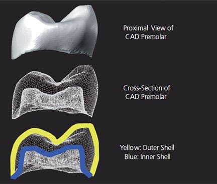
Digital design software takes into consideration two distinct surfaces of a digital restoration, the outer and inner shells (Figure 1). The outer shell is the proposed anatomic shape of the restoration that can be altered by the clinician or laboratory technician with software editing tools. The inner shell of the restoration is automatically designed by the CAD software, as influenced by operator-determined parameters (e.g., cement gap and horizontal margin excess), as well as the shape and diameter of the milling tool. Although clinicians can change the parameter settings the software will use to influence the shape of the inner shell, they cannot use tools to edit selective areas of the inner shell. The resulting space between the inner and outer shells defines the thickness of the final restoration.
It is well documented that compromising the thickness of all-ceramic materials can result in catastrophic bulk fracture of the material.10 To achieve predictable outcomes with CAD/CAM all-ceramic restorations, the clinician must factor both clearance from the opposing dentition and the mechanical requirements of the CAM process in the final material thickness.
Unfortunately, the thickness of the final restoration is not simply the distance from the external shell to the surface of the preparation. The restoration’s internal shell may not simply follow the preparation shape, but could include contours to make it machinable by the milling unit cutting it from the raw material. This final internal shape must allow complete and passive seating of the restoration, with acceptable margins after milling is complete. The process in which the internal shell is designed for compatibility with the burs in the milling unit is called drill compensation.11 The amount of drill compensation is determined by:
- Tool shape (flat or round end)
- Tool diameter11–13
- Material substrate (i.e., hardness or softness of the raw material)11,14
![Image of what to consider when determining estoration’s ideal internal shape]()
FIGURE 2. Drill compensation is an important consideration when determining the restoration’s ideal internal shape.
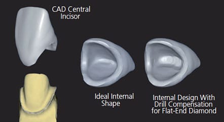
With digital dentistry, the clinical significance of drill compensation is demonstrated in the case illustrated in Figure 2 and Figure 3. This maxillary central incisor presents challenges to the CAD/CAM process because the milling tool’s shape/diameter is not well matched to the preparation shape. The preparation results in a thin incisal edge, as required by facial and palatal material reduction requirements. The milling tool being used to create the internal surface of the crown in this scenario is a 1.2-mm flat-end diamond. As drill compensation is applied for a chairside milling unit, the CAD software enlarges the internal surface to accommodate the diameter and shape of the milling tool.1,11 This creates excess cement space, but ensures complete marginal seating of the restoration.11
preparation and any compensation needed for the drill or milling tools used in the case.
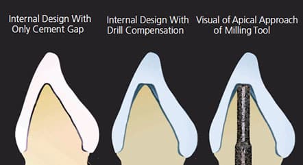
In this scenario, the restoration’s final material thickness becomes much thinner due to overmilling from the applied drill compensation (Figure 3).1,11 This can be frustrating to the clinician who reduced the tooth to achieve minimum thickness requirements for the material, but ended up with a compromised material thickness due to the overmilling requirement of the CAM process.1 The resulting internal shape of the restoration in Figure 3 is poor for use with glass ceramic materials. It has reduced thickness, as well as increased cement space — potentially reducing the effectiveness of resin adhesion to reinforce the restoration.15,16 Additionally, overmilling by the flat-ended bur results in a radial shoulder cut into the internal surface of the restoration, which creates the potential for stress concentration at the thinnest portion of the restoration.2,17 These three factors combine to reduce the durability of a glass ceramic restoration, and could negatively affect the restorative outcome, despite proper reduction by the clinician.
A method to anticipate the effects of drill compensation is to envision the milling tool approaching from the apical side of the tooth preparation to subtractively mill out the internal surface of the crown, as illustrated in Figure 3. The milling tool selectively removes material from the block and will follow the shape of the tooth preparation. Selecting a smaller milling tool diameter allows more intricate preparation features to be reproduced in the crown and will minimize overmilling; however, it will require more milling time, and the tool may lose its cutting efficiency and require more frequent replacement.
TOOTH PREPARATION GUIDELINES FOR CHAIRSIDE GLASS CERAMIC RESTORATIONS
Compared to other materials, glass ceramic commonly used for single-visit restorations has more stringent occlusal and margin width thickness requirements to successfully withstand the forces of occlusion. For adhesive restorations, the thickness requirement is 1 mm for lithium disilicate and it can go up to 2 mm for traditional glass ceramics on posterior cusps.17,18 The leading clinical failure of these materials is bulk fracture, which is directly correlated with the thickness of the ceramic material.2 Traditional strength estimates for a monolithic glass ceramic correlate the resistance to fracture being proportional to the square of its thickness.2 Overmilling that reduces material thickness by 50% could lead to a proportional four times reduction in fracture resistance.19 To prevent this type of unexpected loss of thickness from drill compensation, follow these preparation guidelines.
Posterior Teeth:
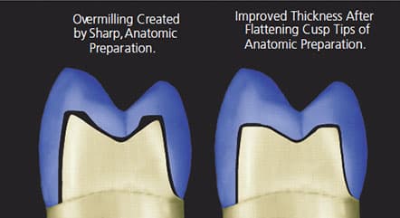
1. Perform anatomical reduction for adequate material thickness in the central groove area. Flatten the resulting sharp cusp tips, as demonstrated in Figure 4 to eliminate overmilling and enhance ceramic thickness.11
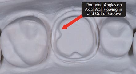
2. When utilizing boxes or grooves in the preparation, eliminate sharp corners that cannot be produced by a milling tool.11,12,20 Sharp corners at the junction of a groove and axial wall will produce significant overmilling. Consequently, the clinician should round these corners to flow smoothly from the axial wall into the groove, as depicted in Figure 5.11
Anterior Teeth:
1. To predict the relative thickness of the tooth before it is prepared for a full-veneer restoration, measure faciolingual width of anterior teeth at the junction of the middle and incisal one-third. If thickness measures less than 3.5 mm, the incisal edge of the preparation may be too thin to accommodate a 1.2-mm flat-ended milling tool.21
2. Try to keep the incisal edge of the preparation flat and as wide as possible (1.5 mm or more) without compromising vertical height of the preparation needed for resistance and retention. Consider the ultra-translucent zirconia materials described in the next section for more favorable manufacturing results.
TOOTH PREPARATION GUIDELINES FOR ZIRCONIA RESTORATIONS
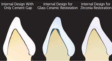
In contrast to glass ceramic materials, the effects of drill compensation/overmilling on the internal shape of zirconia restorations are barely visible. Figure 6 demonstrates an anterior restoration with ideal, uniform cement gap, glass ceramic drill compensation, and zirconia drill compensation. The similarity between the ideal gap and zirconia is obvious — this dramatic improvement stems from the milling of zirconia in an enlarged dimensional state. The blocks milled in a chairside or laboratory milling machine are partially-sintered zirconia, and volumetrically shrink approximately 25% to 30% during the sintering process.22 Milling an enlarged restoration presents a significant advantage to zirconia, effectively reducing the diameter of milling tool the same 25% to 30%. Additionally, partially sintered zirconia is easy to mill (considered “soft machining”) and produces minimal tool wear.11 These two factors yield a small, almost nonexistent drill compensation, as demonstrated in Figure 6. This makes ultra-translucent zirconia an excellent replacement material for glass ceramics on anterior teeth that often have thin and sharp incisal edges after proper facial and palatal reduction.
When restoring posterior teeth with monolithic zirconia, the minimal impact of overmilling enables more anatomic preparations, without the negative effects of drill compensation.23 Due to the effect of the restoration shrinking by 25% during the sintering process, clinicians do not need to factor in the requirements of the CAM subtractive manufacturing process as much as they do when using glass ceramics.
CONCLUSIONS
The process used to make all-ceramic restorations with a CAD/CAM workflow is efficient and predictable facet of restorative dentistry. However, the subtractive manufacturing process requires minor tooth preparation modifications that differ from tooth preparations using the lost-wax technique. To ensure optimal material characteristics, clinicians should make adjustments to tooth preparations to minimize the effect of drill compensation and the risk of overmilling. As previously noted, overmilling can result in bulk material fracture due to the development of internal stresses at sharp transitions, reduced material thickness, and an increased thickness of resin cement.
When treatment planning for a glass ceramic material to restore an anterior or posterior tooth, the preparation geometry of incisal edges and cusp tips must be rounded and large enough to fit the drill that is being used in the subtractive manufacturing process. If the tooth preparation geometry cannot be reproduced during milling and will result in overmilling, the clinician may wish to consider changing the treatment plan from a glass ceramic material to a full-contour translucent zirconia. Because the translucent zirconia shrinks approximately 25% during sintering, the process of sintering effectively reduces the impact of drill compensation and overmilling.
Subtractive manufacturing techniques for all-ceramic restorations have more than 30 years of documented clinical success.24 As more clinicians adopt chairside CAD/CAM workflows and manufacture restorations in-house, it will be important to have an understanding of the milling process and material selection to achieve predictable and durable clinical outcomes.
KEY TAKEAWAYS
- The process of subtractive manufacturing used in the computer aided design/computer aided manufacturing (CAD/CAM) workflow significantly differs from the lost-wax technique for creating indirect restorations. An understanding of the process will allow providers to apply concepts in tooth preparation that are best suited for a specific manufacturing technique and achieve optimal fit and material performance from CAD/CAM-processed restorations.
- It is well documented that compromising the thickness of all-ceramic materials can result in catastrophic bulk fracture.10
- To achieve predictable outcomes with CAD/CAM all-ceramic restorations, the clinician must factor both clearance from the opposing dentition and the mechanical requirements of the CAM process in the final material thickness.
- The final internal shape must allow complete and passive seating of the restoration, with acceptable margins after milling is complete.
- The use of zirconia materials for preparations with thin or sharp geometry can reduce overmilling and improve material thickness and, subsequently, strength of the restoration.
REFERENCES
- Abduo J, Lyons K, Bennamoun M. Trends in computer-aided manufacturing in prosthodontics: a review of the available streams. Int J Dent. 2014;783948:1–15.
- Rekow D, Zhang Y, Thompson V. Can material properties predict all-ceramic crown survival? Compendium. 2007;28:304–311.
- Sadid-Zadeh R, Li R, Miller L, Simon M. Effect of fabrication technique on the marginal discrepancy and resistance of lithium disilicate crowns: an in vitro studyJ J Prosthodont. 2019:28:1005–1010.
- Sadid-Zadeh R, Li R, Patel R, Makowa S, Miller L. Impact of occlusal intercuspal angulation on the quality of/C/D/CAM lithium disilicate crowns. J Prosthodont. January 12, 2019. Epub ahead of print.
- Sadid-Zadeh R, Katsavochristou A, Squires T, Simon M. Accuracy of marginal fit and axial wall contour for litium disilicate crowns fabricated using three digital workflows. J Prosthet Dent. 2020;123:121–127.
- Anadioti E, Aquilion S, Gratton D, et al. 3D and 2D marginal fit of pressed and CAD/CAM lithium disilicate crowns made from digital and conventional impressions. J Prosthodont. 2014;23:610–617.
- Huang Z, Zhang L, Zhu J, Zhao Y, Zhang X. Clinical marginal and internal fit of crowns fabricated using different CAD/CAM technologies. J Prosthodont. 2015;24:291–296.
- Dolev E, Bitterman Y, Meirowitz A. Comparison of marginal fit between CAD/CAM and hot-press lithium disilicate crowns. J Prosthet Dent. 2018;121:124–128.
- Mahmood DJ, Braian M, Larsson C, Wennerberg A. Production tolerance of conventional and digital workflow in the manufacturing of glass ceramic crowns. Dent Mater. 2019;35:486–494.
- Goodacre CJ, Bernal G, Rungcharassaeng K, Kan JY. Clinical complications in fixed prosthodontics. J Prosthet Dent. 2003;90:31–41.
- Örtorp A, Jönsson D, Mouhsen A, Vult von Steyern P. The fit of cobalt-chromium three-unit fixed dental prostheses fabricated with four different techniques: a comparative in vitro study. Dent Mater. 2011;27:356–363.
- Beuer F, Schweiger J, Edelhoff D. Digital dentistry: an overview of recent developments for CAD/CAM generated restorations. Br Dent J. 2008;204:505–511.
- Rekow D, Erdman A, Riley D, Klamecki B. CAD/CAM for dental restorations — some of the curious challenges. IEEE Trans Biomedl Eng. 1991; 38:314–318.
- Kikuchi M, Okuno O. Machinability evaluation of titanium alloys. Dent Mater J. 2004;23:37–45.
- May LG, Kelly JR, Bottino MA, Hill T. Effects of cement thickness and bonding on the failure loads of CAD/CAM ceramic crowns: multi-physics FEA modeling and monotonic testing. Dent Mater. 2012;28:99–109.
- Tuntiprawon M, Wilson PR. The effect of cement thickness on the fracture strength of all-ceramic crowns. Aust Dent J. 1995;40:17–21.
- VitaBlocs Working Instructions. Available at: https://www.vitanorthamerica.com/datei.php?src=download/Support/Instructions-For-Use/Machinables/VITABLOCS-Working-Instruct_o_s_1769E.pdf. Accessed February 14, 2020.
- Ivoclar Vivadent, Adhesive 1mm Crown. Available at: http://downloads.ivoclarvivadent.com/zoolu-website/media/document/38982/IPS+e-max+CAD-IPS+e-max+Press+-+Adhesive+1mm+crown. Accessed February 14, 2020.
- Rosenstiel SF, Land MF, Fujimoto J. Contemporary Fixed Prosthodontics. St. Louis: Saunders Elsevier Health Sciences; 2006.
- Sadan A, Blatz MB, Lang B. Clinical considerations for densely sintered alumina and zirconia restorations — part 1. Int J Periodontics Restorative Dent. 2005;25:213–219.
- Chiche G. Esthetics of Anterior Fixed Prosthodontics. Battavia, Ill: Quintessence Publishing; 1994.
- Denry I, Kelly JR. State of the art of zirconia for dental applications. Dent Mater. 2008;24:299–307.
- Nakamura K, Harada A, Inagaki R, et al. Fracture resistance of monolithic zirconia molar crowns with reduced thickness. Acta Odontol Scand. 2015;73:602
- Posselt A, Kerschbaum T. Longevity of 2328 chairside Cerec inlays and onlays. Inter J Comput Dent. 2003;6:231–248.
Capt. Peter R. Barndt, DDS, MDSc, FACP, has no commercial interests to disclose. Stephen J. Sterlitz, DDS, MS, ABGD, and Dennis J. Fasbinder, DDS, ABGD, disclose having received grants, research support and honorarium from Dentsply Sirona, 3M and Ivoclar.
From Decisions in Dentistry. March 2020;6(3):16-18,21.
