Exploring Dynamic Computer-Assisted Implant Surgery
Dynamic navigation systems improve the accuracy and efficiency of implant placement.
This course was published in the October/November 2024 issue and expires November 2027. The authors have no commercial conflicts of interest to disclose. This 2 credit hour self-study activity is electronically mediated.
AGD Subject Code: 690
EDUCATIONAL OBJECTIVES
After reading this course, the participant should be able to:
- Discuss the differences between static and dynamic computer-assisted implant surgery and how each impacts implant placement accuracy.
- Identify the advantages of dynamic navigation systems.
- Recognize the learning curve and financial investment required for implementing dynamic navigation systems in dental implant surgery.
With the growing popularity of implant therapy, one of the biggest challenges is placing the implant in the correct position using a prosthetically driven approach.1 Traditionally, implant placement was based on a freehand approach, which involves transferring the preplanned implant position to the clinical situation using only adjacent and opposing teeth as a reference. This led to marked implant positional deviations.2 Malposition of implants is often associated with complications.3-6 The difficulty of visualizing an ideal position and angulation has encouraged dentists to adopt advanced technology for more accurate implant placement.
In recent years, computer software that aids in the three-dimensional (3D) planning of implants has been developed. These computer-assisted technologies have helped dental surgeons place implants in the desired restorative position, by utilizing cone-beam computed tomography (CBCT) with or without intraoral or extraoral optical surface scans (IOS/EOS).7
Computer-assisted implant surgery improves the accuracy of implant placement, especially in anatomically complex sites, reducing the risk of complications.8 Currently, two types of computer-assisted implant surgery exist: static computer-assisted implant surgery (s-CAIS) and dynamic computer-assisted implant surgery (d-CAIS).
S-CAIS uses software that virtually plans the implant position based on the CBCT and IOS/EOS data. A surgical guide is then designed and printed based on the virtual implant location. Subsequently, this surgical guide is fixed on the appropriate area to support the surgeon in placing the implant. On the other hand, the d-CAIS is a real-time navigation tool that continuously tracks sensors fixed on the patient’s mouth and surgical instruments. It displays the surgical site and the implant drill on a computer screen with data on the 3D deviation between the drill and the virtual plan in real time.
The advantages of d-CAIS include:9,10
- Data collection (CBCT), virtual implant planning, and implant surgery can all be completed in one day.
- Increase in accuracy, safety, and predictability of implant placement.
- Ability to view the drill location and deviation from the planned position in real time and adjust the implant location and size during the procedure.
- Good accessibility when there is insufficient interocclusal space for a static surgical guide and armamentarium.
Navigation systems for oral and maxillofacial surgery are mainly based on optical tracking technology. The patient will have devices attached to his/her jaw and on the handpiece used during surgery. These devices will have light-emitting diodes or passive reflecting tracking elements that are tracked by the stereoscopic optical camera and guided by the preplanned implant position on the CBCT. The accuracy of these optical tracking systems usually lies between 0.1 and 0.4 mm (Figure 1).11,12
Fiducial Clip and Image Acquisition
In partially edentulous patients, an impression of the teeth is taken by a fiducial marker (Figure 2A). To take that impression, the fiducial clip (X-clip) is placed in a hot water bath at a temperature of 140° to 160 °F for 3 to 5 minutes until the thermoplastic material is clear and then an impression is taken on the opposite side of the same arch that the implant is to be placed, as to not interfere with the drilling of the implants (Figure 2B).
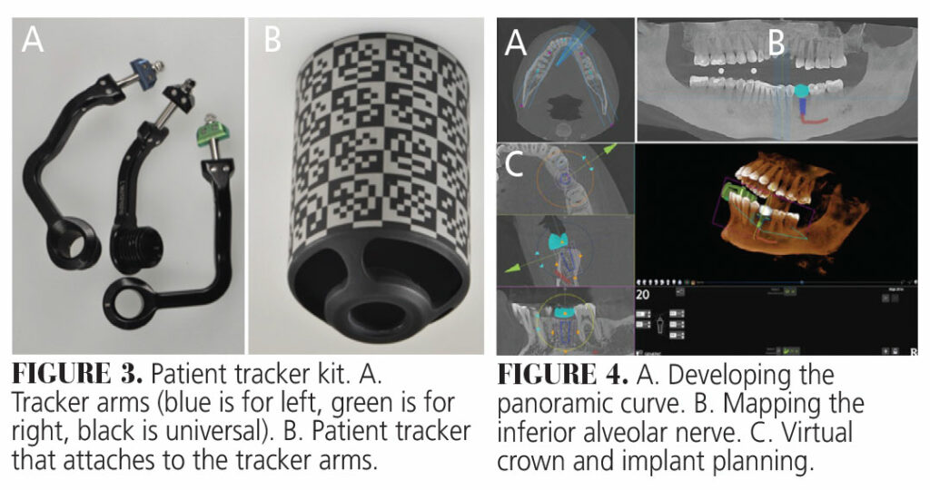
Once an impression is taken, the fiducial is removed and placed in cold water; it is then tried on again in the patient’s mouth to confirm stability and accuracy. The clinician must ensure that whenever the fiducial is taken out, it is placed back into the same location in the patient’s mouth to ensure registration is accurate (Figure 2C). Once the fiducial is confirmed to be stable in the patient’s mouth, the clinician then takes a CBCT of that jaw with the fiducial marker in place (Figure 2D). The fiducial marker has an area to which the tracker arms and the patient tracker attach. This allows for live tracking during the surgery of the patient’s anatomy as displayed in the CBCT (Figure 3).
Software Planning
Once the “digital imaging and communications in medicine” (DICOM) data are obtained from the CBCT, the images are uploaded into the treatment planning software. A panoramic curve of the arch needing implants is developed on the axial plane of the CBCT scan. On the mandible, the inferior alveolar nerve can be traced. When available, IOS images of the patient can be merged into the DICOM data to allow better soft tissue evaluation. A virtual crown can also be added to allow for restoratively driven implant planning. The software allows for generic implant placement or the choice to customize the size of the implant and abutment height/angle (Figure 4).
Calibration, Registration, and System Check
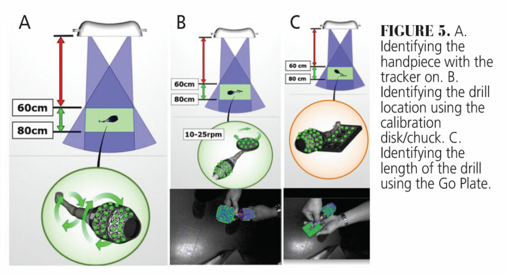
Calibration is the process that the dynamic navigation system uses to register the tools and patient anatomy in reference to the CBCT scan and virtual implant plan. The geometry of the passive reflective elements on the patient and handpiece trackers allows them to be detected by the stereoscopic optical cameras as shown in Figure 1. The parts need to be assembled and then placed in front of the optical cameras to allow the software to “learn” their geometry. The calibration process usually occurs at 60 to 80 cm from the camera. The calibration involves the handpiece calibration and the X-clip calibration/registration.
The first step of the handpiece calibration is to hold the assembled handpiece with the tracker on under the camera and rotate it to allow the camera to identify the patterns on the handpiece tracker. This is followed by hooking the calibration disk/chuck onto the implant handpiece head and running the drill motor at 10 to 20 revolutions per minute. This “teaches” the machine the location of the handpiece in relation to the center of the disk/chuck, which is where the drill bit starts. The last step involves placing an implant drill onto the handpiece and allowing it to touch the go plate. This “teaches” the machine to locate the tip of the drill in relation to the handpiece, and hence the length of the drill (Figure 5)
The X-clip calibration involves placing the assembled patient tracker under the stereoscopic cameras so it can read the patterns on the patient tracker and relate them to the fiducial markers on the X-clip. An implant drill is then placed on the handpiece and the drill bit is placed on the three fiducial spheres on the X-clip. This is how the patient’s anatomy on the CBCT scan is registered in relation to the tracker (Figure 6).
All these steps can be done before the patient’s arrival. Once the patient arrives, before the surgery begins, and after the change of every drill, the clinician must perform a system check. A critical step in the workflow, system checks ensure that the tracking system is working accurately. With every drill change, the clinician places his/her surgical drill on the Go Plate and then touches the drill on distinct clinical landmarks, such as adjacent teeth or bone. If the drill radiographically correlates to the clinical position, then the calibration and registration are correct and the dentist can proceed with the surgery (Figure 7).
Navigation Surgery
Once the system check is complete, the dentist can place the drill over the planned surgical site. The navigation screen allows the clinician to view the virtual drill along with the measurement of depth in tenths of a millimeter, the angular deviation from the planned implant axis, and the implant timing. The tip of the drill is represented as a very small blue dot that the dentist can place over the center of the targeted implant virtual position.
Drilling can be initiated, and the clinician can visually see where the drill is going compared to his/her virtual implant plan. The depth of the drill is usually indicated by color. It starts with green, and when the dentist is 0.5 mm from the targeted depth, it turns yellow. The yellow will then turn into a red to indicate the planned depth has been reached. Throughout the procedure, the assistant can keep an eye on the clinical site and notify the surgeon of any changes that occur from the virtual implant plan. The clinician can change the implant dimension and/or location as he/she sees fit, depending on intraoperative factors.
Surgical Case
A 45-year-old woman presented to the Center of Implant, Esthetic, and Innovative Dentistry at Indiana University School of Dentistry, with a chief complaint of “I want to replace my lower missing tooth,” pointing at the lower left second premolar (#20). The medical history showed no contraindication to surgical implant placement.
An X-clip impression was taken on the lower right canine to the second premolar area. The clip was taken out and placed back into the patient’s mouth to verify that it was stable and not easily dislodged. A CBCT was then taken of the lower jaw with the clip still in the patient’s mouth. The DICOM data obtained from the CBCT were then uploaded onto the navigation system’s computer and a restoratively driven implant plan was completed.
The handpiece tracker was attached to the handpiece and calibrated into the system. A green (right) tracker arm was attached to the X-clip and the patient tracker was screwed on it and a patient tracker calibration was performed. The X-clip was placed back into the patient’s mouth with the tracker attached to it (Figure 8). A full-thickness flap was reflected on the area of interest and a system check was performed prior to implant surgery and with every drill change (Figure 7). After drilling the last drill, a guide pin was placed to verify the location osteotomy (Figure 9).
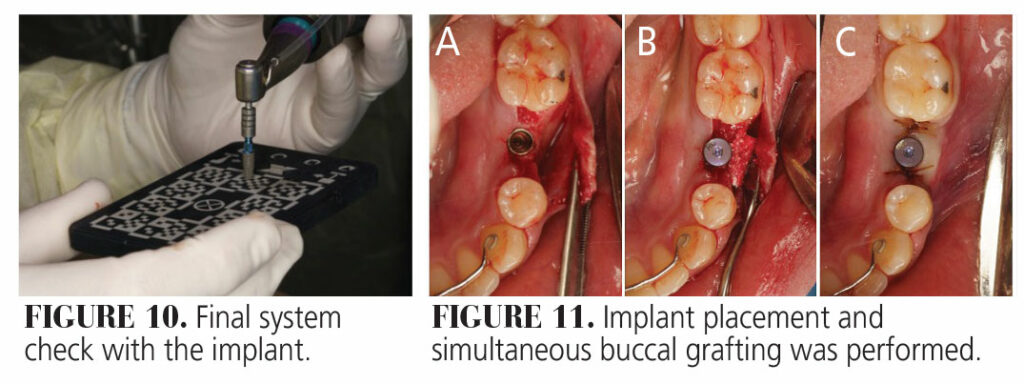
The implant was placed on the handpiece and a final system check was done (Figure 10). The implant was then placed into the prepared osteotomy site. Due to a slight buccal concavity and thin buccal bone, the surgeon opted to graft that site. A healing abutment was placed, and the site was sutured (Figure 11).
Final Considerations
Both dynamic and static computer-assisted surgery techniques result in more precise implant placement and reduce errors compared to freehand methods.13 However, more clinicians are utilizing d-CAIS for multiple reasons. In addition to its high accuracy, the workflow is very efficient and fast. The patient can have the implant placed on the same day, without any delay due to surgical guide fabrication as is required with CAI-S. The surgeon is also not limited to a static guide, in case he/she wants to change the implant size or location due to unexpected intraoperative clinical situations.
If the system check confirms the accuracy of calibration and registration, the clinician also has the option to perform the implant surgery in a flapless manner, thus minimizing trauma to the patient. Furthermore, with s-CAIS, the clinician cannot verify the accuracy in real time, he/she usually has to place the implant and then perform an IOS to compare its actual location with the preplanned location. With d-CAIS, however, the clinician can verify the real-time deviation from the planned position and make adjustments accordingly. Studies have shown similar to slightly better accuracy of shoulder, apex, and angular deviations in d-CAIS when compared to s-CAIS.10,14,15
Dynamic navigation is also ergonomically more advantageous when compared to any other surgery, as the patient is looking at the screen, rather than bending down to look into the patient’s mouth. Moreover, a big benefit of dynamic surgery is in cases of limited mouth opening. The d-CAIS allows for guided implant placement without the need for additional armamentarium that is involved in the s-CAIS (surgical guide, drill handles).
Clinicians should also keep in mind the cost involved in dynamic navigation. Dynamic navigation is a significant investment. In addition to the capital cost, there is the additional per-case expense of the implant planning and X-clips. Learning any new technology can be challenging, but the learning curve is especially steep with dynamic navigation systems. Based on the literature, surgeons become efficient in d-CAIS only after placing 10 to 20 implants.16 The choice of whether to utilize a s-CAIS or d-CAIS workflow will inherently depend on the clinician’s financial capability, level of comfort, and training. Both techniques are great in overcoming the limitations of human vision and increasing the accuracy and precision of implant placement.
References
- Katsoulis J, Pazera P, Mericske‐Stern R. Prosthetically driven, computer‐guided implant planning for the edentulous maxilla: a model study. Clin Implant Dent Relat Res. 2009;11:238-245.
- Smitkarn P, Subbalekha K, Mattheos N, Pimkhaokham A. The accuracy of single‐tooth implants placed using fully digital‐guided surgery and freehand implant surgery. J Clin Periodontol. 2019;46:949-957.
- Romandini M, Lima C, Pedrinaci I, Araoz A, Soldini MC, Sanz M. Prevalence and risk/protective indicators of peri‐implant diseases: A university‐representative cross‐sectional study. Clin Oral Implants Res. 2021;32:112-122.
- Chen ST, Darby IB, Reynolds EC. A prospective clinical study of non‐submerged immediate implants: clinical outcomes and esthetic results. Clin Oral Implants Res. 2007;18:552-562.
- Gamborena I, Avila‐Ortiz G. Peri‐implant marginal mucosa defects: Classification and clinical management. J Periodontol. 2021;92:947-957.
- Cavallaro J, Greenstein G. Prosthodontic complications related to non-optimal dental implant placement. Dental Implant Complications–Etiology, Prevention, and Treatment Ames, Iowa: Wiley-Blackwell; 2010:156-171.
- Tahmaseb A, Wismeijer D, Coucke W, Derksen W. Computer technology applications in surgical implant dentistry: a systematic review. Int J Oral Maxillofac Implants. 2014;29:25-42.
- Widmann G, Bale RJ. Accuracy in computer-aided implant surgery — a review. Int J Oral Maxillofac Implants. 2006;21:305-313.
- Gargallo-Albiol J, Barootchi S, Salomó-Coll O, Wang Hl. Advantages and disadvantages of implant navigation surgery. A systematic review. Ann Anat. 2019;225:1-10.
- Wu D, Zhou L, Yang J, et al. Accuracy of dynamic navigation compared to static surgical guide for dental implant placement. Int J Implant Dent. 2020;6:78.
- Khadem R, Yeh CC, Sadeghi-Tehrani M, et al. Comparative tracking error analysis of five different optical tracking systems. Comput Aided Surg. 2000;5:98-107.
- Koivukangas T, Katisko JP, Koivukangas JP. Technical accuracy of optical and the electromagnetic tracking systems. Springerplus. 2013;2:1-7.
- Block MS, Emery RW. Static or dynamic navigation for implant placement — choosing the method of guidance. J Oral Maxillofac Surg. 2016;74:269-277.
- Zhou M, Zhou H, Li SY, Zhu YB, Geng YM. Comparison of the accuracy of dental implant placement using static and dynamic computer-assisted systems: an in vitro study. J Stomatol Oral Maxillofac Surg. 2021;122:343-348.
- Wang F, Wang Q, Zhang J. Role of dynamic navigation systems in enhancing the accuracy of implant placement: A systematic review and meta-analysis of clinical studies. J Oral Maxillofac Surg. 2021;79:2061-2070.
- Block MS, Emery RW, Cullum DR, Sheikh A. Implant placement is more accurate using dynamic navigation. J Oral Maxillofac Surg. 2017;75:1377-1386.
From Decisions in Dentistry. October/November 2024;10(6):32-35.


