Achieving Esthetic Excellence With an Immediate Implant Placement in the Anterior Zone
This case report illustrates the successful application of the 10 keys for immediate implant placement in the esthetic zone. By following a meticulous, evidence-based approach, the team delivered optimal esthetic and functional outcomes, with a final follow-up showing long-term stability and patient satisfaction.
In 2017, Levine et al1 introduced the “10 keys,” an evidence-based treatment algorithm for successful and predictable placement of immediate implants in the esthetic zone. The updated 10 keys address the major pre-, peri- and postoperative aspects of immediate implant placement and temporization that promote optimal long-term esthetic and functional success. The following case report describes the utilization of the 10 keys in the planning and execution of an immediate implant in the anterior esthetic zone.

A 37-year-old healthy, nonsmoking man was referred by his prosthodontist to a periodontist following loss of the post-core-crown restoration on tooth #9 (Figures 1A and 1B). The patient reported seasonal allergies and acid reflux and was taking esomeprazole. Intraoral examination showed minor gingival inflammation of tooth #9; however, clinical probing depths were normal (≤ 3 mm). The mid-buccal fracture was near the osseous crest. No periodontal diseases or caries were evident, and no parafunctional habits or tooth mobility were noted.
Several treatment options — including their advantages and disadvantages — were presented and discussed with the patient. As the adjacent teeth were unrestored, the patient elected to pursue dental implant replacement of tooth #9.
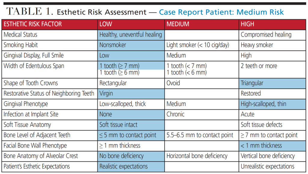
A preoperative esthetic risk assessment2 (Table 1) was completed (Key No. 1) and identified a thin buccal wall phenotype. Due to the low lip line and realistic expectations, the patient was classified as a medium esthetic risk. As the patient was being managed by an experienced multidisciplinary team, it was decided in consultation with the patient that an immediate implant and provisional crown could be delivered with optimal esthetic results — provided the additional nine keys were applied.
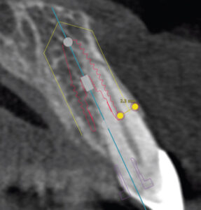
A cone-beam computed tomography (CBCT) image of the maxilla showed an intact, but thin, buccal plate on tooth #9 (Key No. 2). Apical and lingual bone were available to provide primary stability. Implant placement was planned digitally (Figure 2). A 4.1×12 mm bone-level tapered implant was planned in a palatal position, allowing a gap between the implant and buccal plate, and the implant shoulder was positioned 1 mm apical to the height of the buccal plate, ensuring adequate “running room” to create an ideal emergence profile4 in a screw-retained position.
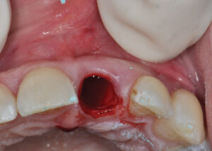
Following appropriate anesthesia, the tooth was extracted with a flapless approach (Key No. 3; Figure 3). The socket was thoroughly curetted and irrigated to remove all soft tissue remnants. The buccal plate was confirmed intact, albeit thin. If the buccal plate was damaged, the risk for future esthetic complications significantly increases and, as such, immediate implant placement would have been aborted. The decision would be either a ridge preservation procedure followed by late implant placement, or early implant placement at 2 months post-extraction to reduce the chance of an esthetic complication.

With the aid of an anatomically correct surgical guide, a regular-diameter implant (4.1 mm) was placed in a palatal position (Key nos. 4 and 5) and 1 mm below the height of the buccal plate. Excellent insertion torque (> 35 Newton centimeters) was achieved.
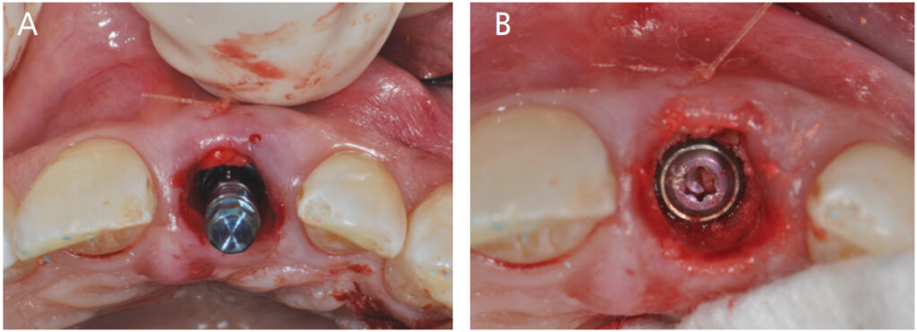
A full-thickness tunnel was created on the buccal aspect, and a connective tissue graft from the palate was inserted and stabilized with a resorbable suture to augment the soft tissue thickness (Key No. 7; Figure 4A). While it is important to follow the 10 keys in sequential order, Key nos. 6 and 7 are the exception, as once the buccal wall is preserved, the execution order of these two steps is up to the treating clinician. In this case, CTG was done prior to grafting for ease of surgical access and to ensure that graft particles were not included in the soft tissue space. The space between the buccal plate and implant was then grafted (Key No. 6) with a 50/50 mix of surgical-grade calcium sulphate and a mineralized allograft (Figure 4B).
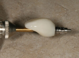
An impression was made, and a tall healing abutment (5.5 mm width x 6.0 mm height) was placed. A lab-processed, screw-retained acrylic resin provisional restoration was fabricated by the prosthodontist and delivered the day after surgery (Key No. 8). Attention was given to the critical and subcritical contours, providing support to the healing soft tissue4 (Figures 5A through 5C). All occlusal contacts were removed in maximum intercuspation and excursive movements. After a 3-month healing period, minor adjustments to the contours of the provisional restoration were made to appropriately mimic the adjacent tooth and its soft tissues facially and interproximally.

Due to patient factors, the temporary prosthesis was left in function for 2 years. Then, a final impression was completed utilizing the custom impression coping technique to allow for the duplication of the developed emergence contour in the final restoration (Key No. 9; Figure 6). A final screw-retained restoration was provided and inserted (Key No. 10).
Follow-up at 5 years (Figures 7A through 7C) demonstrates adequate pink and white esthetics; however, a slight grey hue was present in the midfacial gingival tissues. A CBCT scan demonstrated maintenance of the buccal bone in the coronal portion; however, remodeling was evident in the mid apical region that did not impact the esthetics and health of the implant.
References
- Levine RA, Ganeles J, Gonzaga L, et al. 10 Keys for successful esthetic-zone single immediate implants. Compend Contin Educ Dent. 2017;38:248–260.
- Chappuis V, Martin W. Implant Therapy in the Esthetic Zone — Current Treatment Modalities and Materials for Single-tooth Replacements.Vol 10. Batavia, Illinois: Quintessence Publishing; 2017.
This information originally appeared in Robert A Levine, DDS, Jeffrey Ganeles, DMD, David P. Semeniuk, BDSc, MS, Debora R. Dias, DDS, MSc, Ping Wang, BDS, PhD, DMD, Harry Randel, DMD and Maurício G. Araújo, DDS, MSc, PhD. Immediate Implant Placement With Virtual Planning in the Esthetic Zone. Decisions in Dentistry. January 2022;8(1):9-12.
