

Use of CAD/CAM Technology in Restorative Practice
Digital dentistry can be combined with conventional techniques in the provision of restorations, implants and multiunit prostheses.
Digital dentistry can be combined with conventional techniques in the provision of restorations, implants and multiunit prostheses
Second in a two-part series: This is the second article in a two-part series. Appearing in the May 2018 issue (available here), Part 1 of this two-part series offers an overview of computer aided design/computer aided manufacturing (CAD/CAM) applications in dentistry, with an emphasis on restorative care. This concluding installment will take a closer look at utilizing CAD/CAM technology in restorative practice — including dental implants, as well as singe- and multiunit prostheses — and the feasibility of successfully integrating conventional techniques with digital dentistry.
PATIENT A: ONLAY AND INLAY
Patient A presented to the prosthodontics clinic at the University of Maryland School of Dentistry for comprehensive care. A thorough oral evaluation included updating radiographs, which showed recurrent caries on teeth #14 and #15. After a discussion of the findings and treatment options, the patient elected for an onlay for tooth #14 and inlay for #15.
The existing restoration on tooth #14 was removed, as were all dental caries. The remaining tooth structure was deemed appropriate for an onlay, and lithium disilicate (LD) was chosen to be milled as the restorative material. Similarly, the existing restoration was removed from tooth #15, and a caries control was completed. The tooth was deemed restorable, and after discussing benefits and limitations of various materials (namely, LD versus gold), the patient elected gold due to its longevity and tooth #15 not posing esthetic concerns.

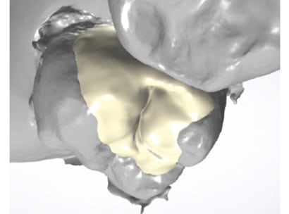
Once completed, the preparation of each tooth was captured using an intraoral scanner. Two scans were obtained (one scan was done per appointment). A digital design was created for each tooth: one for milling and the other for printing (Figure 1 and Figure 2, respectively).
For tooth #14, the onlay was milled using a four-axis milling machine. The onlay was stained, glazed and crystallized in an appropriate furnace.
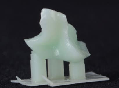
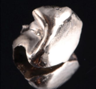
For tooth #15, the completed inlay design was exported as a standard tessellation language (STL) file. Three-dimensional (3D) software programming was used to set up the design for printing, which was done in a castable resin using a 3D printer. The printed resin (Figure 3) was invested in a universal investment material. Type III gold was used to cast the inlay (Figure 4).
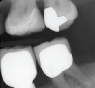
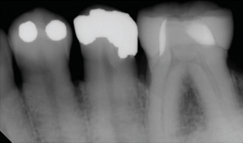
At the try-in appointment, interproximal contact between the onlay and inlay was appropriate, without the need for adjustment. The fit of the onlay was appropriate, as well — although the gold inlay required minor adjustments. Occlusion was appropriate in maximal intercuspation, without the need for adjustment, except in excursive movements on the inlay. Once the patient approved the appearance, resin cement was used to bond the onlay, while zinc phosphate cement was chosen for the inlay. Radiography was used to verify the fit of each restoration (Figure 5).
PATIENT B: REMOVABLE, FIXED AND IMPLANT PROSTHESES
Patient B presented to the university clinic with partially edentulous maxillary and mandibular arches — Kennedy Class I and Class II, respectively — with implants at sites #5, #12 and #29.
The treatment plan for Patient B was to fabricate an implant-retained removable partial denture (RPD) for the maxillary arch, a crown on tooth #19, and an implant-supported crown on site #29.
A border molding was completed using modeling plastic impression compound and a custom tray. A medium-viscosity polysulfide impression material was used make a master impression of the maxillary arch. The master cast was recovered using a Type III stone. The cast was scanned with a desktop scanner so the RPD framework could be digitally designed.
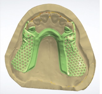
The digitized master cast was analyzed for undercuts, which were blocked out digitally. The completed digital design of the RPD metal framework was sent as an STL file to a laboratory for fabrication (Figure 6).
The RPD framework was tried for fit and retention, which were appropriate. A wax rim was made on the framework to obtain proper facebow and maxillo-mandibular relationship records. Maxillary master cast and mandibular diagnostic cast were mounted on a semi-adjustable articulator.
A crown preparation was completed on tooth #19. After placing a scan body at implant site #29, a digital impression was made for tooth #19, as well as the implant (Figure 7). The digital impression was sent to the laboratory for fabrication of custom abutment for site #29. The custom abutment was tried to verify fit clinically and radiographically. Although the custom abutment’s fit was verified, it was determined the finish line of the abutment did not have the adequate width to allow the minimum thickness of LD. At this point, two options were considered: either digitally redesigning the abutment and having a new abutment milled, or refining the existing abutment and coronal restoration design. Because scanner was available in the clinic, the latter option was chosen.

Prior to refining the abutment, the custom abutment was picked up using an additional silicone elastomeric impression material. The impression included tooth #19, as well. This pick-up impression not only ensured the proper positioning of the custom abutment, it also allowed try-in of all the milled restorations. The custom abutment was prepared to allow a sufficient thickness of LD, and the refined abutment was rescanned.
Crowns were digitally designed and milled using LD blocks in a low translucency shade A2. The crowns were evaluated on the cast in their blue stage. After making minor adjustments in the interproximal contacts, the crowns were stained, glazed and crystallized. The crystallization process required 17 minutes at a firing temperature of 820 degrees Celsius. The resulting crowns were tried again on the cast.
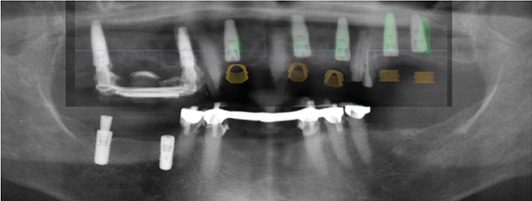
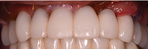
During the delivery appointment, the maxillary implant-retained RPD was tried first. Pressure-indicating paste was used to identify and adjust pressure areas. Retention, stability and support were deemed appropriate. The locator metal housings were placed on the locator abutments and picked up using an autopolymerizing resin. The resulting retention on the implant locator abutments was satisfactory. The crowns were evaluated for appropriate interproximal contacts and marginal adaptation clinically, and radiographs were obtained to verify the fit (Figure 8 and Figures 9).
A minor adjustment was needed for proper occlusion. The patient was happy with the esthetics and comfort of all of the prostheses (Figure 10). Following the manufacturer’s cementation protocol, the crowns were bonded with resin cement. All excess cement was removed. Homecare instructions were given to the patient, and a follow-up appointment was made.
PATIENT C: IMPLANT PROSTHESES
Patient C presented to the university clinic with both maxillary and mandibular arches restored in long-span provisional fixed partial dentures (FPDs) with the following implants and remaining teeth:
- Implant sites #2, #5, #29 and #31
- Teeth #6, #9, #13, #20, #21, #22, #27 and #28
The existing provisional FPDs were evaluated for vertical dimension, esthetics, phonetics, and occlusion, which were all appropriate.

The provisional FPDs were removed to evaluate the condition of the abutment teeth, which were deemed restorable. Before recementing the FPDs, full-volume cone beam computed tomography (CBCT) imaging was obtained by minimizing the potential scatter from the metal reinforcement present in the FPDs. Due to a scanner not being available, a decision was made to make impressions of the maxillary and mandibular arches with irreversible hydrocolloid impression material, both with and without the provisional FPDs. Type III stone was used to make diagnostic casts from the impressions. The casts were mounted and diagnostic wax-up was completed.
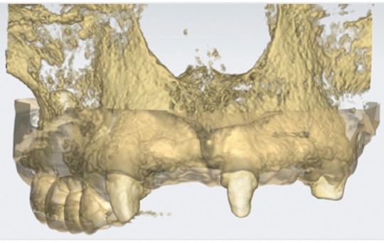
All casts were eventually digitized with the desktop scanner and digitally merged with the CBCT image (Figure 11). After discussing the options, benefits and limitations, the treatment plan was to place implants at sites #7, #10, #12, #14, #15, #18 and #19. One major benefit of this option was that it preserved existing natural dentition. One major limitation, on the other hand, was a lack of bony support on the labial aspect of sites #7, #10 and #12 when regular-diameter (4.3-mm) implants were planned digitally. For this reason, a consultation was made with a periodontist for grafting at the time of implant placement. The patient consented to the grafting procedure. The final restorative plan consisted of implant- and tooth-supported FPDs.
The guide was designed over the implant-supported provisional FPD (sites #2 to #5) and teeth #6, #9 and #13. The guide design was exported to the printing software and printed in-house with a 3D printer. Noble metal sleeves (appropriate for a fully guided surgical drill protocol) were placed in the guide (Figure 12), and the printed guide was cured in the curing unit. Following curing, the sleeves were reinforced with cyanoacrylate (injected through small openings on the palatal side), and sleeve stability was checked.
Implants at sites #14 and #15 were placed first using the guide, and the implant mounts were kept in place to provide additional stability to the guide (Figure 12). Next, implants at sites #7, #10 and #12 were placed utilizing the guide.

After removing the guide, the periodontist made the full-thickness flap from teeth #6 to #13, and intramarrow penetration was done prior to placing the bone graft and membrane. Freeze-dried bone allograft was mixed with deproteinized bovine bone mineral particles in 1:1 ratio, followed by Type I collagen membrane (Figure 13).

To achieve primary closure, a combination of chromic gut (4-0), vicryl (5-0) and prolene (6-0) sutures were used. Postsurgical radiography was obtained, and the presurgical plan was superimposed on the postsurgical radiograph to evaluate placement accuracy (Figure 14).
The existing provisional FPD was tried to ensure it would not place pressure on the grafted sites. Slight pressure was observed in the pontic areas, and the provisional FPD was relieved accordingly. After verifying occlusion and polishing, the FPD was cemented with provisional cement (Figure 15). The patient reported being comfortable and was subsequently discharged.
DISCUSSION
The workflow for Patient A could have been purely digital had she requested a milled inlay for tooth #15, obviating the need to conventionally cast the gold inlay. It is important to note that digitally designing and printing or milling resin patterns offers advantages over conventional wax-ups. The CAD/CAM resin patterns are not as susceptible to temperature changes as conventional casting waxes, and, as a result, are less prone to distortion.1 Thus, if casting was not feasible in-office, the resin pattern could be safely shipped to a laboratory for casting.
While studies have examined the fit of CAD/CAM ceramic restorations and conventional restorations (e.g., using the lost wax technique), various factors — including technique — can influence fit. For example, Anadioti et al2 found that when a digital impression was combined with a conventional method (a pressed LD in the study), the internal fit of the resulting restorations was less accurate than those made with strictly conventional or digital techniques. Other studies, however, show different results. For instance, Zeltner et al3 noted that conventionally manufactured crowns had better fit than digitally made crowns. In the presence of contradicting results and absence of long-term, large-scale studies, determining fit accuracy based on type of workflow is a clinical challenge.
In the case of Patient B, much of the workflow involved conventional steps, such as maxillo-mandibular relationship and try-in of the crowns on tooth and implant abutments — yet clinicians could consider scanning and digitizing these relationship. In addition, the custom abutment could be scanned in the laboratory for designing and fabricating the implant crown, either before or after the abutment try-in.
Unlike the patient example in this article, a scanner could be used instead of conventional impressions by taking digital impressions of both soft tissue and prepared RPD abutment teeth. Proponents suggest the advantage of using the digital impression is that it can be accurate without placing pressure on the soft tissue.4 Others contend conventional impressions for a full arch achieve more accurate results than digital methods.5 The accuracy and predictability of digital full-arch impressions is likely to improve in the future thanks to fast-changing technology. In addition, because RPD metal frameworks can be manufactured using various materials and methods (including casting, milling or selective laser sintering), it is worthwhile to examine how different materials and methods affect framework quality.6
Finally, the workflow for Patient C could be provided mostly digitally by obtaining a full-mouth intraoral scan (with and without the provisional FPDs), and digitally designing the diagnostic wax-up. Implant placement guide design could vary, depending on the supporting structure (either the abutment teeth or provisional FPD). The guide design shown in Figure 15 was supported by both the implant provisional FPD and teeth #6, #9 and #13. Here, the guide could be made partial by only seating on the teeth. Since tooth-borne implant placement guides are known to be more reliable than mucosa-borne, the accuracy of the guide most likely is unaffected by the supporting structure used, and whether it is a partial or full arch.7,8 Regardless of variation in the tooth-borne guide design, it is important to note that implant positioning and guide design were based on the prosthetic vision.
How workflow is designed for a given patient varies based on multiple factors, including the types of restorations planned, availability of a scanner and compatible digital support, and clinician preference. Though there is little evidence supporting (or refuting) the practice of combining conventional and digital methods, integrating techniques is feasible, sensible, and even needed in certain situations (as shown in these case examples).
CONCLUSION
As discussed in the first article of this two-part series, the dental team must bear in mind that workflows should be based on accurate diagnoses and prognoses, as well as meticulous planning that centers on the patient’s best interests. This concluding installment presents treatment examples that utilize digital technology. Each example involved both conventional and digital methods, based on planning and prosthodontic principles. As technology continues to advance, it will be exciting to see how digital dentistry can further improve treatment and outcomes.
ACKNOWLEDGEMENT
The author offers sincere thanks to:
- Robert Choe, DMD, for providing the treatment and its documentation for Patient B.
- Priscilla Sia, BDS, MS, and William Wahle, DDS, MS, for treatment planning; Hanae Saito, DDS, MS, CRC, and John Davliakos, DMD, for their guidance; and Jack Ji Chao, BDS, MS, for performing the grafting procedure for Patient C.
- Carl Driscoll, DMD, and Radi Masri, DDS, MS, PhD, for their guidance throughout all treatment presented in this paper.
- Most importantly, our patients.
REFERENCES
- Masri R, Driscoll CF, editors. Clinical Applications of Digital Dental Technology. Hoboken, NJ: John Wiley & Sons; 2015:76,133.
- Anadioti E, Aquilino SA, Gratton DG, et al. Internal fit of pressed and computer-aided design/computer-aided manufacturing ceramic crowns made from digital and conventional impressions. J Prosthet Dent. 2015;113:304–309.
- Zeltner M, Sailer I, Mühlemann S, Özcan M, Hämmerle CH, Benic GI. Randomized controlled within-subject evaluation of digital and conventional workflows for the fabrication of lithium disilicate single crowns. Part III: marginal and internal fit. J Prosthet Dent. 2017;117:354–362.
- Mansour M, Sanchez E, Machado C. The use of digital impressions to fabricate tooth‐supported partial removable dental prostheses: A clinical report. J Prosthodont. 2016;25:495–497.
- Ender A, Attin T, Mehl A. In vivo precision of conventional and digital methods of obtaining complete-arch dental impressions. J Prosthet Dent. 2016;115:313–320.
- Campbell SD, Cooper L, Craddock H, et al. Removable partial dentures: The clinical need for innovation. J Prosthet Dent. 2017;118:273–280.
- Geng W, Liu C, Su Y, Li J, Zhou Y. Accuracy of different types of computer-aided design/computer-aided manufacturing surgical guides for dental implant placement. Int J Clin Exp Med. 2015;8:8442–8449.
- Ramasamy M, Giri RR, Subramonian K, Narendrakumar R. Implant surgical guides: From the past to the present. J Pharm Bioallied Sci. 2013;5 (Suppl 1):S98–S102.
Featured image by ZORANM/E+/GETTY IMAGES PLUS
From Decisions in Dentistry. July 2018;4(7):23—27.
