

Mapping the Maxillary Sinus
The following technique can be used to enhance lateral window sinus lift bone augmentation procedures.
The following technique can be used to enhance lateral window sinus lift bone augmentation procedures
This article describes a method to efficiently accomplish a lateral window sinus lift bone augmentation. The technique is unique, because it is predicated on creating a blueprint (i.e., mapping the maxillary sinus) to make osseous cuts through the buccal plate of bone based on a cone beam computed tomograph (CBCT) scan. Four defined sites, designated as points A, B, C and D, are used to delineate the extent of the lateral window (anteriorly, posteriorly, superiorly and inferiorly). This information is transferred from the CBCT scan to the patient using fixed reference points, such as a tooth or tack.
Mapping the maxillary sinus facilitates placement of accurate osseous cuts to create a lateral window and soft tissue incisions to expose the surgical field. The discussion also includes techniques to create the lateral window, insert bone into the sinus, and manage complications associated with lateral window sinus lifts.
An atrophic posterior maxilla requires bone augmentation to enable insertion of dental implants. The alveolar ridge may need osseous grafting bucco-lingually and/or apico-coronally prior to implant placement. Correction of the first situation involves horizontal guided bone regeneration. The latter condition is resolved with a lateral wall sinus augmentation (sinus lift) or a transcrestal sinus floor elevation.1 Clinicians have suggested that if there is <4 mm of bone subantrally, a lateral wall sinus lift is the most predictable method to regenerate bone to support dental implants in the maxillary sinus.2,3
Mapping the maxillary sinus is a prerequisite for initiating therapy because it facilitates planning and performing a precise, step-by-step technique. In addition, this article presents pertinent information regarding sinus anatomy and management of common complications associated with sinus lifts.
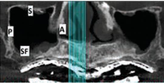

view of the right sinus, the arrow points to ostium, which is the opening from the sinus into the middle meatus of the nose.
UNDERSTANDING ANATOMY
Pyramidal in shape, the maxillary sinus is the largest paranasal sinus. Its dimensions are typically as follows: height 36 to 45 mm, antero-posterior length 25 to 35 mm, and latero-medial depth 38 to 45 mm.4 The maxillary sinus is bordered by six walls:5 (Figure 1).
- Anterior wall contains blood vessels to the anterior teeth, plus the infraorbital nerve and artery
- Superior wall is the floor of orbit and is very thin
- Posterior wall separates the sinus and pterygopalatine fossa; items in this region include the posterior superior alveolar nerve and blood vessels, plus the pterygoid plexus of veins and internal maxillary artery
- Medial wall partitions the sinus from the nasal fossa; the blood supply to the medial wall comes from nasal mucosal vasculature
- Sinus floor is a bony wall that sometimes extends between the roots of the maxillary bicuspids and molars
- Lateral wall forms the buccal aspect of the sinus and contributes to the posterior maxillary and zygomatic process; this wall provides access for the lateral wall sinus graft procedure
Clinicians should also be familiar with other anatomic structures before performing a sinus lift. On the medial wall (in the first molar area), the ostium facilitates drainage of the sinus into middle meatus of the nasal cavity. The average distance from the most inferior aspect of the antral floor is 28.5 mm (Figure 2).6 Accordingly, the sinus should not be filled with bone beyond 15 mm from the antral floor to preclude the possibility of blocking the ostium and causing a sinusitis. Septa are found in 31% of the maxillary sinuses and are usually located on the medial wall in the premolar area.7 They rarely fully compartmentalize the antrum. The thickness of the Schneiderian membrane that lines the sinus cavity is usually 0.3 to 0.8 mm,8 but it may be thicker if chronic inflammation causes a hyperplastic reaction. If the membrane is very thick (e.g., 20% of the sinus height), it is prudent to obtain an ear/nose/throat consult before initiating a sinus graft. The 20% measure is the authors’ recommended threshold for obtaining a consult; others may wish to consult for smaller increases in membrane thickness.

After an extraction in the sinus region, the sinus may expand internally within six months due to pneumatization.9 A radiographic investigation can determine the amount of sinus expansion that happens after tooth extractions (e.g., first molar 0.98 mm; multiple teeth 2.22 mm).9 When examining cross sections of a CBCT scan, detection of radiolucency in the buccal plate denotes the presence of an intraosseous blood vessel (Figure 3).10 The infraorbital artery provides the blood supply to the anterior part of the sinus.11 This vessel anastomoses with the posterior superior alveolar artery within the buccal plate of bone (intraosseous artery) and in the buccal tissues (extraosseous artery).11 In approximately 20% of cases, the intra osseous artery in the lateral wall of the sinus is less than 16 mm from the crest of the ridge; thus, it may need to be managed during a lateral window preparation.12
PLANNING A SINUS LIFT
If sinus augmentation is required to place dental implants in the maxilla, it is prudent to obtain a CBCT scan of the maxillary arch in order to plan the procedure. The scan helps identify locations of anatomical structures and facilitates creating a detailed blueprint for executing the sinus lift. Making the blueprint or drawing is referred to as mapping the sinus (Figure 4). It consists of identifying and recording where osseous cuts and soft tissue incisions will be performed. Prior to initiating therapy, vertical osseous cuts to develop the lateral window in the buccal plate of bone must be calculated. Clinicians then plan the location of soft tissue incisions to adequately expose these bony cuts.
For the sake of this discussion, a sinus lift is planned for the maxillary right posterior sextant. Teeth numbers 1 to 5 are missing, and the maxillary sinus extends to the mesial of where the second bicuspid was previously located, and posteriorly to the distal aspect of the second molar (Figure 4). Please note that while the guiding principles described with respect to mapping osseous cuts and soft tissue incisions apply to other clinical scenarios, the location of the bony cuts and soft tissue incisions will vary depending on the clinical situation (e.g., location and size of the sinus and/or presence of teeth).
The following steps will help provide bone in the sinus so implants can be placed to support the prosthesis:
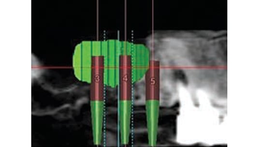
- Plan the prosthesis: In the case depicted in Figure 4, the restoration will be supported by two implants placed into the right maxillary sinus (site numbers 3 and 4) and at Site 5 (Figure 5)
- Select implant positions on the panoramic/cross-sectional slices of the CBCT scan
- Visualize graft material extending 3 to 5 mm beyond implant positions (Figure 5)
- Map the sinus to facilitate planning osseous cuts to create a lateral window into the sinus
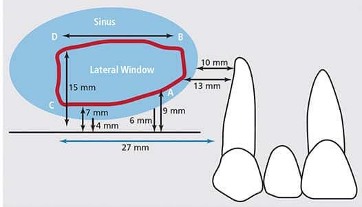
Measurements related to the lateral window are made on the CBCT panoramic view. The distances are calculated from fixed reference points on the scan (in this example, distal of the canine or from identified points), so they can be transferred to the patient. Four precise locations — points A, B, C and D — are used to demarcate the extent of the lateral window (Figure 4). The following instructions specify how to select the vertical and horizontal locations for each point.
Point A (inferior point of anterior vertical osseous cut): On the CBCT scan, measure how far distal to the canine is the lowest point on the anterior wall of the sinus; next, go 3 mm distal and 3 mm coronal to the floor of the sinus. This is Point A. In Figure 4, the anterior wall of the sinus is 10 mm distal to the canine and the alveolar ridge is 6 mm tall. Therefore, Point A is 13 mm distal to the canine and 9 mm superior to the residual alveolar crest of bone. Note, Point A is positioned 3 mm distal to the anterior wall of the sinus and 3 mm coronal to the floor of the sinus to ensure that osseous cuts are made over the sinus, and not above bone.
Point B (superior point of anterior vertical osseous cut): Measure on the CBCT scan from Point A to the most superior location the graft must occupy to encase the length of the planned implants (in this case, 2 mm of bone is desired apical to 13 mm implants). Thus, Point B is 15 mm from the osseous crest — or, stated another way, 6 mm superior to Point A (9 + 6 mm = 15 mm) (Figure 4). A line drawn from Point A to Point B delineates the anterior vertical cut, which follows the contour of the anterior wall of the sinus. Due to variations in sinus anatomy, this cut may curve to remain approximately 3 mm distal to the anterior wall of the sinus.
Point C (inferior point of posterior osseous cut): Horizontally, Point C is located on the CBCT scan by measuring from Point A or distal of the canine to the most posterior location needed to surround the planned implants with grafted bone; then come coronal to the floor of the sinus by 3 mm to determine its vertical location. In Figure 4, implants are to be placed to restore the first molar (#3), second bicuspid (#4) and #5. Therefore, the most posterior aspect of the lateral window, Point C, is 27 mm distal to the canine (assuming the molar is around 11 mm wide and the bicuspids are 8 mm wide mesio-distally). Calculated another way, Point C is 14 mm posterior to Point A, which was 13 mm from the canine (for a total of 27 mm). Point C is 7 mm superior to the crest of the alveolar ridge, because there was a 4-mm-tall alveolar ridge and it is desirable to be 3 mm coronal to the bone when making an osseous cut. Line A–C delineates the inferior horizontal cut of the osteotomy (Figure 4). But because the residual alveolar bone often varies in height, the inferior bone cut is usually not a straight line.
Point D (superior point of posterior osseous cut): On the CBCT scan, measure from Point C or the osseous crest to the most superior location the graft must occupy to encase the length of the planned implants within bone (13 mm implants, in this case). This is Point D. Line C–D delineates the posterior vertical cut of the osteotomy (Figure 4). In this example, Point D is 8 mm superior to Point C, or 15 mm (7 + 8 mm = 15 mm) superior to the osseous crest. By default, line B–D delineates the superior horizontal cut of the lateral window osteotomy, and is approximately 14 mm long.
When the Schneiderian membrane is elevated, it will be released several millimeters under the bone beyond the vertical osseous cuts in all directions. Thus, the size of the bone graft will be larger than the prepared lateral window. Taking this into account, clinicians have the option of making the window smaller than originally planned. Conversely, some therapists may choose to enlarge the lateral window to improve access. With respect to using a fixed reference point to transfer measurements, if the maxillary arch is edentate, a tack can be placed slightly anterior to the sinus bellows prior to initiating the osseous cuts, and a CBCT or periapical image can be taken. This will provide a landmark to help plan and execute osseous cuts and soft tissue incisions. Alternately, a surgical guide with radiopaque markers can be used to establish reference points.
Another facet of creating the lateral wall relates to the thickness of the lateral bony plate. On CBCT cross sections, clinicians should assess and record the thickness of the lateral bony plate, as it may be a factor in how the lateral window is prepared.
SOFT TISSUE INCISIONS
Soft tissue incisions must provide adequate room for creation of the lateral window, and leave enough bone exposed in case it is desirable to alter its shape (e.g., >4 mm of exposed bone circumferentially around the lateral window in all directions). For the scenario described in Figure 4, soft tissue incisions are placed as follows. Vertical incisions to the vestibule should be made 4 mm mesial to where the anterior vertical osseous cut will be made (using the canine as a reference point, the incision is made 6 mm distal to the canine), and 4 mm distal to where the posterior vertical osseous cut will be made (31 mm from the canine). Next, a mid-crestal ridge incision is made connecting the vertical incisions. It is desirable to make the horizontal incision in keratinized tissue to facilitate suturing. Anteriorly and posteriorly, vertical soft tissue incisions are created so the base of the flap is slightly wider than the coronal aspect of the pedicle flap; this provides a good blood supply to the elevated soft tissue. After the incisions are made, a full thickness mucoperiosteal flap is elevated approximately 19 mm apical to the crest of the osseous ridge. Note, the flap design described is for 13-mm-long implants; if 10 mm implants were placed, the flap would be elevated approximately 16 mm (implant 10 mm, additional 2 mm of bone beyond the implant, and 4 mm of additional bone exposure). When the flap is raised, the bellows of the maxillary sinus (buccal bulge) will be obvious. Clinicians should be aware the infraorbital nerve emerges approximately 5 mm below the infraorbital rim. The flap rarely needs to be elevated this superiorly; as a result, this nerve will seldom be damaged.
CREATING THE LATERAL WINDOW
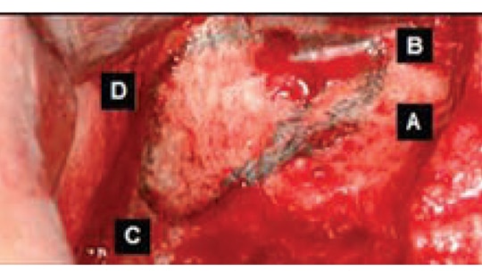
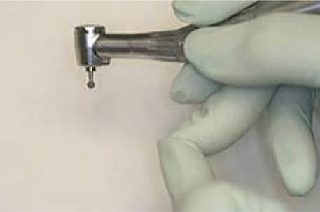
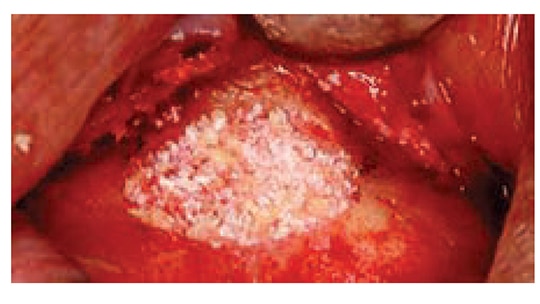
After flap elevation, a sterile Number 2 pencil is used to mark points A, B, C and D (Figure 6). The points are connected to demarcate the outline of the lateral wall window on the buccal plate of bone. Several instruments can be used to create the window. If using a bur, it is preferable to use a #8 round diamond (surgical length) until the bluish Schneiderian membrane is seen (Figure 7). A round carbide bur (#6) should not be used because it is too coarse and might tear the membrane. Initial detection of the bluish color does not mean the membrane has been reached, as typically there still is some bone that must be removed. A diamond bur can be employed on its side (horizontally) or vertically to create the lateral window. Horizontal utilization helps avoid pressing too hard and penetrating into the sinus. The window outline can also be created with an ultrasonic device (e.g., piezoelectric ultrasonic surgery unit).13 The bur or piezo tip is used circumferentially around the window until the outlined lateral bony window becomes mobile.
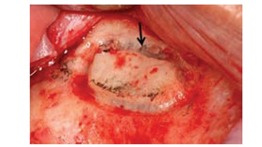
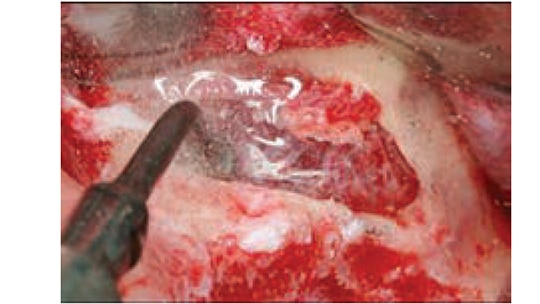
Using an instrument, the clinician touches the island of demarcated bone to determine which part of the outline needs additional bone removal to achieve its circumferential depressabilty. Once the membrane is elevated, if this island of bone is retained it will become the roof of the sinus lift. This cannot be done, however, if the latero-medial width of the sinus is narrower than the coronal apical width of the island of bone. When the sinus is narrow and the bony plate cannot be elevated, an alternative method of bone management (assuming the window osteotomy is complete) includes peeling the island of bone off the membrane. This must be done cautiously to avoid tearing the membrane. The osseous lateral window can also be created using an ultrasonic device in a manner that eliminates the entire bony window (Figure 8).
If the buccal plate is thick (>2 mm), it is faster to use a diamond bur to create the outline of the lateral window until the bluish membrane is detected prior to using a piezo tip to complete the release of the bony island; this helps avoid tearing the membrane. When developing a lateral window, it is critically important to use a finger rest when holding the handpiece. If there are no teeth to provide a finger rest on the maxilla, extend the ring finger from the hand that holds the elevator and extend the ring finger from the hand that holds the handpiece; these two fingers should touch at their tips (Figure 9). This will provide a stable finger rest.
the lateral window outline.
After attaining depressabilty of the island of bone (lateral window), the Schneiderian membrane must be elevated circumferentially. Sinus kits are available with tools of various shapes and angles to help release this membrane (Figure 10). If available, it is preferable to initiate membrane release with a piezo unit because it facilitates membrane elevation with ultrasonic waves and helps avoid tears (Figure 8). Although many instruments can be used in a similar manner, a Prichard curet is an effective tool for membrane release. The face of the curet is directed toward the bone and moved along the bone several millimeters at a time. The curved back of the instrument allows the membrane to be elevated as the sharp edge hugs the bone. It is desirable, but not always possible, to elevate the membrane mesially to the anterior wall of the sinus, as this facilitates packing bone against the anterior wall when bone is placed into the sinus. The membrane should be elevated across the sinus floor to the medial wall. The clinician continues to elevate the membrane up the medial wall to approximately the height of the planned implants. This is desirable because the medial wall provides vascularity and progenitor cell for bone regeneration. Superiorly and distally, the membrane is internally elevated off the bone (3 or 4 mm beyond the lateral window) to facilitate raising the membrane from the floor of the sinus to the planned superior level. When creating the osseous cuts anteriorly and inferiorly, it is helpful not to leave more than a 3 mm lip of bone; otherwise, it will impair visualization and make it more difficult to elevate the membrane. It also increases the risk of instruments slipping off the bone and tearing the membrane.

INTRODUCING BONE INTO THE SINUS
is used to insert bone into the sinus.
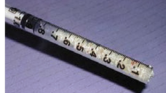
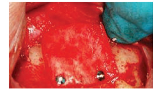
To reduce potential intrasinus contamination, the instruments used to place bone into the sinus should be separated from implements used to elevate the membrane (which are subject to salivary contact). Usually 2 to 4 grams of bone substitute are needed to complete a sinus lift.14 Bone is hydrated with saline and loaded into a tuberculin syringe (Figure 11). When bone is inserted into the sinus, it is pushed against bone. If the anterior wall was reached during the elevation procedure, the bone in the syringe is directed against the anterior wall and sinus floor. Next, particulate bone is compressed with a bone condenser. The clinician continues filling bone anteriorly and toward the floor until the space created under the Schneiderian membrane is filled (Figure 12). It is not necessary to load bone superiorly or posteriorly with force because the membrane might tear. After the sinus is filled with bone, a collagen barrier is placed on the outer aspect of the bone graft; it should extend 2 to 3 mm circumferentially beyond the bone graft. The barrier can be tucked under the flap before suturing, but if the barrier is displaced upon flap closure, it can be tacked in place (Figure 13). Alternately, a suture can be used at the base of the flap, which can be extended over the barrier and sutured to the palatal tissue to hold the barrier. Finally, primary closure is attained, and, after six to nine months of healing, the implants can be placed.
COMMON COMPLICATIONS
As with any oral surgery, clinicians face potential complications when performing maxillary sinus elevation. The most frequent problem is perforating the Schneiderian membrane as it is elevated (which occurs in approximately 25% to 40% of cases)15 or when burs are used to create the lateral window.16 Although it is difficult to reengage the membrane if a tear occurs along the periphery of the osteotomy, this can be managed by extending the outline of the osteotomy several millimeters beyond the original window and reestablishing contact with the membrane (Figure 14). If a tear occurs during the sinus lift procedure and it is a small defect (1 to 2 mm), a resorbable wound dressing can be placed over the perforation. If the perforation is >2 mm, the opening can be patched with a piece of resorbable collagen barrier that’s large enough to cover the tear by several millimeters. Before placement, the collagen barrier should be hydrated to soften it. Utilization of a piezo unit reduces the incidence of membrane perforations.13 Schwartz-Arad et al16 found that intraoperative complications, such as membrane perforation, did not negatively impact implant survival. Another complication involving membrane tears is beyond the scope of this paper: If the membrane is perforated beyond repair during elevation, techniques are available to artificially create a pouch to retain a bone graft.17

When performing an osteotomy, excessive bleeding can occur for several reasons. It is possible, for example, to cut a blood vessel that runs along the membrane, or sever an intraosseous artery in the lateral wall of the sinus. Bleeding from the membrane can be controlled by placing gauze soaked with anesthetic solution containing 1/50,000 epinephrine directly onto the membrane. Bleeding from the bone requires application of direct pressure with an instrument (e.g., hemostat), or it can be managed with a cautery unit. Another method for containing an intraosseous arterial bleeder is to displace the membrane and compress the bone with a mosquito hemostat, thereby crushing the bone and obstructing the bleeding blood vessel.
Septa may be found in the maxillary sinus, which can complicate elevating the membrane. The majority of septa are located between the second premolar and first molar area.7 When the membrane is to be raised over partial septa, they should be elevated from the lateral toward the medial, because septa frequently increase in size as they move medially, and membrane elevation anteriorly to posteriorly over septa is more apt to result in membrane perforation. If there is a full partition of the sinus by a septum, more than one lateral window is created as part of the antral opening to circumvent the septa.18,19
If an infection without fluctuance occurs after a sinus lift, antibiotics are needed (e.g. levofloxacin or amoxicillin and clavulanate potassium). Once there is fluctuance, incision and drainage is done in combination with prescribing systemic antibiotics.20 It is judicious to culture the infection to assess whether the correct antimicrobial therapy is being used. A chronic infection mandates that the graft material should be removed and the sinus flushed with saline.21 Indicators of sinusitis may include fever, facial pain (which escalates on leaning or bending forward), and yellow to green purulent discharge from the nose (which may drain posteriorly, causing a cough and malaise).21 Additional symptoms include popping of the ears, muffled hearing, possible edema of the periorbital tissues, and referred pain to the maxillary teeth.22 Sinus infections can have serious consequences; rarely, they develop into unilateral or bilateral pansinusitis or a cavernous sinus involvement.
CONCLUDING REMARKS
It is strongly recommended that a CBCT scan be obtained to help plan a lateral window sinus lift. Mapping the sinus in advance facilitates an efficient procedure. It is also advisable to have surgical headlight and a cautery unit available. This technique should not be attempted without proper academic, desktop and clinical training — including sufficient repetition of the procedure with an experienced mentor.
KEY TAKEAWAYS
• The lateral window sinus lift bone augmentation technique described here is predicated on creating a blueprint (i.e., mapping the maxillary sinus) to make osseous cuts through the buccal plate of bone based on cone beam computed tomography.
• Mapping the maxillary sinus is a prerequisite, because it facilitates planning and performing a precise, step-by-step technique.
• Four defined sites, designated as points A, B, C and D, are used to delineate the extent of the lateral window (anteriorly, posteriorly, superiorly and inferiorly).
• After flap elevation, a sterile Number 2 pencil is used to mark points A, B, C and D. The points are connected to demarcate the outline of the lateral wall window on the buccal plate of bone.
• When developing a lateral window, it is critically important to use a finger rest when holding the handpiece.
• If a membrane tear occurs along the periphery of the osteotomy, it is hard to reengage the membrane — but this can be managed by extending the outline of the osteotomy several millimeters beyond the original window and reestablishing contact with the membrane.
• This technique should not be attempted without proper academic, desktop and clinical training.
REFERENCES
- Woo I, Le BT. Maxillary sinus floor elevation: review of anatomy and two techniques. Implant Dent. 2004;13:28–32.
- Zitzmann NU, Schaerer P. Sinus elevation procedures in the resorbed posterior maxilla. Comparison of the crestal and lateral approaches. Oral Surg Oral Med Oral Pathol Oral Radiol Endod. 1998;85:8–17.
- Fugazzotto PA. Augmentation of the posterior maxilla: a proposed hierarchy of treatment selection. J Periodontol. 2003;74:1682–1691.
- van den Bergh JP, ten Bruggenkate CM, Disch FJ, Tuinzing DB. Anatomical aspects of sinus floor elevations. Clin Oral Implants Res. 2000;11:256–265.
- Misch CE. The maxillary sinus lift and sinus graft surgery. In: Misch CE, ed. Implant Dentistry. 2nd ed. St Louis: CV Mosby Co; 1999:469–470.
- Uchida Y, Goto M, Katsuki T, Akiyoshi T. A cadaveric study of maxillary sinus size as an aid in bone grafting of the maxillary sinus floor. J Oral Maxillofac Surg. 1998;56:1158–1163.
- Ulm CW, Solar P, Krennmair G, Matejka M, Watzek G. Incidence and suggested surgical management of septa in sinus-lift procedures. Int J Oral Maxillofac Implants. 1995;10:462–465.
- Mogensen C, Tos M. Quantitative histology of the maxillary sinus. Rhinology. 1977;15:129–140.
- Sharan A, Madjar D. Maxillary sinus pneumatization following extractions: a radiographic study. Int J Oral Maxillofac Implants. 2008;23:48–56.
- Greenstein G, Carpentieri JR, Cavallaro J. Dental cone-beam scans: Important anatomic views for the contemporary implant surgeon. Compend Contin Educ Dent. 2015;36:735–741.
- Kqiku L, Biblekaj R, Weiglein AH, Kqiku X, Städtler P. Arterial blood architecture of the maxillary sinus in dentate specimens. Croat Med J. 2013;54:180–184.
- Elian N, Wallace S, Cho SC, Jalbout ZN, Froum S. Distribution of the maxillary artery as it relates to sinus floor augmentation. Int J Oral Maxillofac Implants. 2005;20:784–787.
- Wallace SS, Mazor Z, Froum SJ, et al. Schneiderian membrane perforation rate during sinus elevation using piezosurgery: clinical results of 100 consecutive cases. Int J Periodontics Restorative Dent. 2007;27:413–419.
- Danesh-Sani SA, Loomer PM, Wallace SS. A comprehensive clinical review of maxillary sinus floor elevation: anatomy, techniques, biomaterials and complications. Brit J Oral Maxillofac Surg. 2016;54:724–730.
- Barone A, Santini S, Sbordone L, Crespi R, Covani U. A clinical study of the outcomes and complications associated with maxillary sinus augmentation. Int J Oral Maxillofac Implants. 2006;21:81–85.
- Schwartz-Arad D, Herzberg R, Dolev E. The prevalence of surgical complications of the sinus graft procedure and their impact on implant survival. J Periodontol. 2004;75:511–516.
- Pikos MA. Maxillary sinus membrane repair: update on technique for large and complete perforations. Implant Dent. 2008;17:24–31.
- Ziccardi VB, Betts NJ. Complications of maxillary sinus augmentation. In: Jensen TO, ed. The Sinus Bone Graft. Chicago: Quintessence Pub Co; 1999:201–208.
- Boyne PJ, James RA. Grafting of the maxillary sinus floor with autogenous marrow and bone. J Oral Surg. 1980;38:613–616
- Regev E, Smith RA, Perrott DH, Pogrel MA. Maxillary sinus complications related to endosseous implants. Int J Oral Maxillofac Implants. 1995;10:451–461.
- Smiler DG. The sinus lift graft: basic technique and variations. Pract Periodontics Aesthet Dent. 1997;9:885–893.
- Sandler NA, Johns FR, Braun TW. Advances in the management of acute and chronic sinusitis. J Oral Maxillofac Surg. 1996;54:1005–1113.
Featured image courtesy of CLAUS LUNAU/SCIENCE PHOTO LIBRARY
From Decisions in Dentistry. December 2016;2(12):12-17.
