
Implant Placement With Augmentation and Osteotomy Sinus Elevation
A case report describing implant placement in a maxillary posterior ridge with deficient horizontal ridge and sinus pneumatization.
A case report describing implant placement in a maxillary posterior ridge with deficient horizontal ridge and sinus pneumatization
After trauma or pathology-related loss of dentition in the posterior maxilla of an implant patient, clinicians face anatomical challenges in placing dental implants in an ideal position. With teeth missing, the alveolar ridge irreversibly resorbs in three dimensions, while the sinus cavity expands. The remaining osseous structures in the maxillary posterior regions are often deficient in quality and quantity for straightforward and predictable implant placement. It is imperative to be intimately familiar with the anatomic relations of posterior maxillary structures during the necessary pre-implant-placement sinus augmentation to avoid surgical complications and injuries.1,2 Careful case selection and preoperative data collection using three-dimensional cone beam computed tomography (CBCT) improve the chances for a successful outcome in augmentation procedures during implant site development.3
A growing number of reconstructive and preprosthetic augmentation techniques and combination therapies have been described and reviewed.4 Guided bone regeneration (GBR),5 sinus elevation (with or without bone expansion),6 block graft,7 particulate graft,8 barrier membranes (resorbable or nonresorbable)9 and distraction osteogenesis10 — even orthodontic eruption of hopeless teeth,11 going as far as posterior maxillary segmental osteotomy12 — have been implemented in maxillary implant site development. The specific clinical case, as well as practitioner skill and preference, will determine the most appropriate treatment modality.
This case report presents the clinical management of a horizontal ridge defect and maxillary sinus pneumatization by sinus floor elevation using osteotomes, and GBR with simultaneous implant placement.
BACKGROUND
Ideal implant placement is guided by the restoration, which, in turn, must satisfy functional and esthetic requirements. That noted, implant position and angulation intrasurgically are determined by the presenting local anatomy and bone morphology at the implant site — which is often unfavorable after long-standing edentulism.
The main postextraction confounding factor associated with posterior maxillary atrophy is the occurrence of sinus pneumatization. It begins as a physiological process during embryogenesis, and normally concludes with the eruption of third molars at approximately 20 years of age. This process is influenced by genetics and previous surgeries, as well as patient metabolism.13–15 The “fourth expansion of the sinus”16 in adult patients after posterior maxillary second molar extractions is caused by a diffuse atrophy of the bone.17 This, in turn, is due to decreased functional loading on the alveolar ridge, which causes bone remodeling homeostasis to shift toward bone resorption. This biological principle is postulated in Wolff’s law,18 which remains largely undisputed.19 It appears, however, that sinus pneumatization only occurs within six months after extraction (as part of socket healing), and does not progress once the previous socket has matured.20 Ridge resorption, on the other hand, is progressive due to lack of functional loading.17
The residual subanterial bone height of the maxilla can be classified in three subanterial classes (SAC):21
SAC 1: Edentulism less than five years; bone height minimum: 10 mm; bone width minimum: 5 mm
SAC 2: Edentulism five to 10 years; bone height: 5 to 10 mm; bone width: between 2.5 and 5 mm
SAC 3: Edentulism more than 10 years; bone height: 0 to 5 mm
While SAC 1 allows for straightforward endosseous implant placement, SAC 2 patients with ridge widths of 2.5 to 5 mm are candidates for sinus lift and GBR procedures before or at the time of implant placement. The treatment plan for SAC 3 patients calls for a staged approach, with delayed implant placement after a healing period post sinus lift and graft maturation.1,21
When considering sinus lifts, the practitioner inevitably encounters the most widely studied internal structure of the maxillary sinus, the septum.22 Perforations of the Schneiderian membrane, which lines the sinus cavity, cause most intraoperative and postoperative complications, and the presence of the septa leads to a higher incidence of perforations.23 Antral septa are classified as primary or secondary. The primary bony projections of the maxillary floor divide the pyramidshaped sinus cavity into compartments. The secondary septa are shorter, protrusive bone spikes into the sinus, which occur following tooth extractions.
The thickness of the Schneiderian membrane is highly variable; in health, it is generally less than 1 mm thick, but it can be more than 2 mm if inflamed.24 Any (even subclinical) sinus pathology, which often manifests in the appearance of the membrane, must be resolved prior to surgical sinus interventions.
CLINICAL PRESENTATION
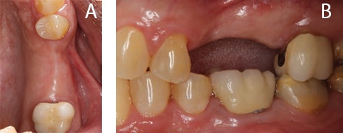
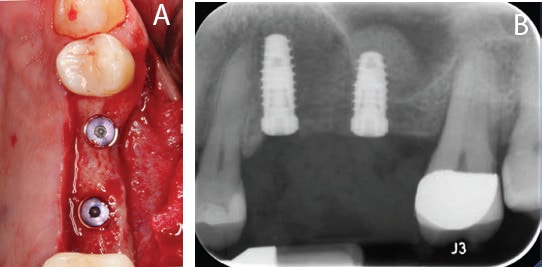
A 67-year-old male nonsmoker with controlled hypertension presented with a referral for implant placement in the maxillary left posterior quadrant. Initial clinical examination revealed missing teeth #13 and #14, with associated localized mild to moderate horizontal and vertical bone deficiency of the ridge (Figures 1A and 1B). The patient had fair oral hygiene, and surrounding teeth presented with mild recession, exposed crown margins and areas of decalcification/discoloration. His dental provider, who had formulated a comprehensive treatment plan, referred the patient. Periapical radiographs of the region are shown in Figures 2A and 2B.
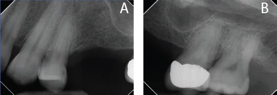
region reveal adequate vertical bone dimensions in the region of #13, but not
around #14 due to sinus pneumatization.
A limited-view CBCT scan provided detailed information regarding the available horizontal and vertical dimensions of the edentulous ridge and proximity of the maxillary sinus, which aided implant selection and planning (Figures 3A through 3C). Virtual placement of the implants can be seen in the figure; as is evident, the buccal plate is very thin when placing the implants in an ideal prosthetic location. Additionally, precise measurements of the sinus location and remaining vertical bone height are critical during placement.25 In this case, 4-mm-diameter implants were selected for both areas, with a 10 mm length chosen for implant #13, and an 8.5 mm length for #14.
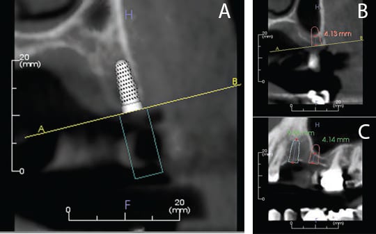
region #13 (A) and region #14 (B and C). A central slice was chosen for each region.
Prior to implant surgery, the patient was advised about the importance of improving oral hygiene, and informed of the clinical and radiographic findings. The necessity of horizontal bone augmentation for region #13 and vertical sinus elevation for region #14 was reviewed, and all questions were answered regarding associated risks, benefits and potential complications. In addition, the patient was reminded of the restorative needs of the surrounding teeth. Lastly, written consent for implant surgery, and ridge and sinus augmentation, was obtained.
CASE MANAGEMENT
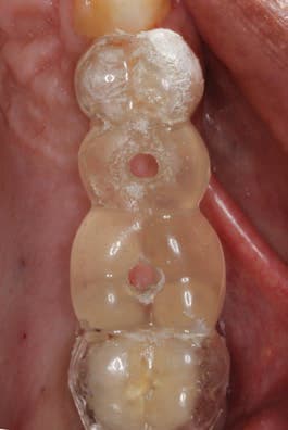
A surgical implant guide was provided by the patient’s primary dentist, who will be restoring the case (Figure 4). This surgical guide proved helpful in determining the appropriate position of the implants, based on the proposed final restorations.
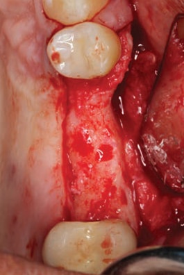
After administration of anesthesia via local infiltrations on the buccal and palatal aspect of the maxillary left posterior region, a 15c blade was used to make three incisions: one crestal incision on the palatal aspect of the edentulous ridge, followed by two vertical incisions on the mesiobuccal line angle of #12, and disto-buccal line angle of #15. Reflection of a full-thickness buccal flap was performed to gain access for implant placement, while the palatal tissues were left intact (Figure 5). As anticipated, the intraoperative clinical photograph reveals a horizontal deficiency in region #13.
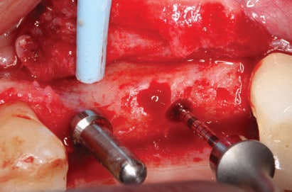
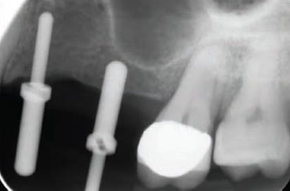
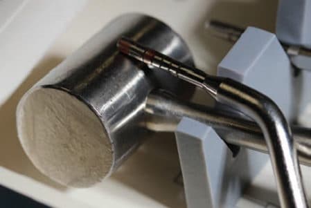
The osteotomy for #13 was first prepared to approximately half of the desired implant depth and a direction indicator was placed, while osteotomy #14 was performed to a depth 1 mm short of the sinus floor.26,27 Confirmation that no sinus perforation had occurred was accomplished using the flat-top periodontal probe shown in Figure 6. A periapical radiograph was subsequently taken to assess location and angulation of the osteotomies, as seen in Figure 7.
The osteotomy #13 was prepared to the final depth and diameter using the appropriate implant drills. For osteotomy #14, only the diameter was initially enlarged; the team then placed a deproteinized bovine bone mineral (DBBM) graft into the osteotomy, which was followed by the use of an osteotome to infracture the sinus floor (Figure 8). Subsequently, additional graft material was introduced, which was elevated vertically using the osteotome to the desired vertical dimension — which is a few millimeters beyond the length of the chosen implant.28
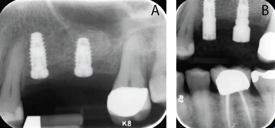
radiograph exposed immediately after the implants were placed and cover screws
inserted, but prior to grafting of the buccal aspect.
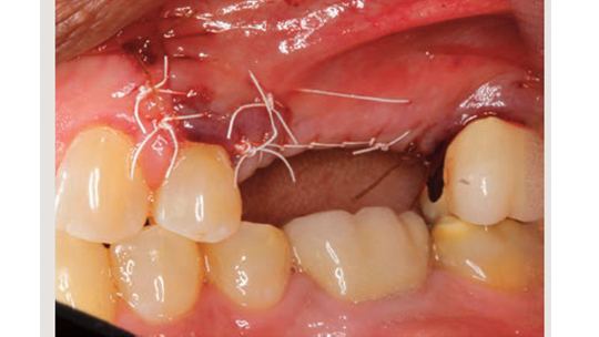
Both implants were placed and achieved primary stability at a torque value of 35 newton centimeters (or Ncm). Cover screws were placed and radiographs were obtained (Figures 9A and 9B). Additional grafting with slow resorbable DBBM was performed on the buccal aspect of #13 and covered with a resorbable 25×25 mm porcine collagen membrane that was extended beneath the palatal tissues for additional stability. A periosteal incision was made in the buccal flap using a new 15 blade, and the flap was adapted and sutured — chiefly with nonresorbable polytetrafluoroethylene sutures and a few resorbable chromic gut sutures (Figure 10).
The patient was placed on a liquid diet for the first 24 hours, followed by a soft diet for the remaining week, and instructed to chew on the right side only. He was also advised to refrain from oral hygiene practices in the surgical site, and rinse with 0.12% chlorhexidine gluconate three times daily for two weeks, take 500 mg amoxicillin every eight hours for seven days, and 400 mg ibuprofen with 500 mg acetaminophen every four to six hours, as needed for discomfort.
CLINICAL OUTCOME AND CONCLUSION
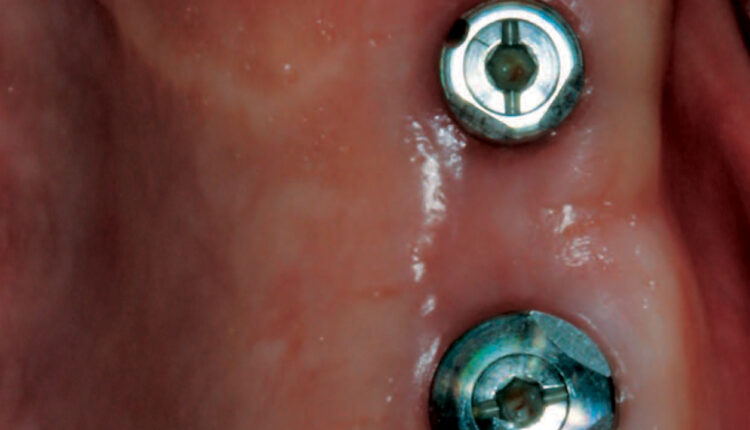
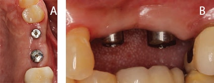
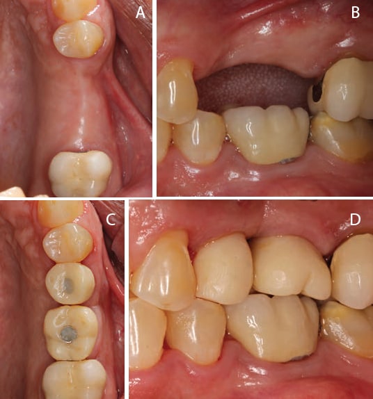
Healing was uneventful and the sutures were removed at the three-week postoperative visit. Second-stage surgery was performed after three months of healing, and radiographs were taken before and after placement of the healing abutments (Figures 11A and 11B). Figures 12A and 12B depict the clinical outcome six weeks after second-stage surgery (at the time of referral back to the restorative dentist). The patient returned for a follow-up visit and presented with provisional crowns on the implants, as seen in Figures 13A through 13D.
In dental implantology, the posterior maxilla presents a clinical challenge due to its morphology and anatomy. Careful consideration of appropriate surgical technique will help ensure predictably successful outcomes. Case selection and practitioner experience are significant determinants of long-term success. It behooves clinicians and patients alike to consider all possible complications intraoperatively and postoperatively, so both can reach informed consent: the patient accepting the risk, and the clinician submitting the patient to the risks and benefits of posterior maxillary implant placement.29 In order to minimize intraoperative injuries and postoperative complications in procedures involving the posterior maxilla, proper diagnosis of the presenting case will help pinpoint the most appropriate surgical approach and increase treatment predictability and success.
KEY TAKEAWAYS
- In dental implantology, the posterior maxilla presents a clinical challenge due to its morphology and anatomy. Careful consideration of appropriate surgical technique will help ensure successful outcomes.
- After trauma or pathology-related loss of dentition in the posterior maxilla of an implant patient, the remaining osseous structures are often deficient in quality and quantity for straightforward and predictable implant placement.
- The specific case, as well as practitioner skill and preference, are factors to consider when choosing the most appropriate treatment modality.
- Implant position and angulation intrasurgically are determined by the presenting local anatomy and bone morphology at the implant site — which is often unfavorable after long-standing edentulism.
- In implant site development, careful case selection and preoperative data collection using cone beam computed tomography improve the chances for a successful outcome during augmentation procedures.3
ACKNOWLEDGEMENT
The authors wish to thank Christopher Aloise, BA, for his assistance in preparing this manuscript.
REFERENCES
- Lee JE, Jin SH, Ko Y, Park JB. Evaluation of anatomical considerations in the posterior maxillae for sinus augmentation. World J Clin Cases. 2014;2:683–688.
- Esposito M, Hirsch JM, Lekholm U, Thomsen P. Biological factors contributing to failures of osseointegrated oral implants. (II). Etiopathogenesis. Eur J Oral Sci. 1998;106:721–764.
- Fortin T, Camby E, Alik M, Isidori M, Bouchet H. Panoramic images versus three-dimensional planning software for oral implant planning in atrophied posterior maxillary: a clinical radiological study. Clin Implant Dent Relat Res. 2013;15:198–204.
- Esposito M, Grusovin MG, Coulthard P, Worthington HV. The efficacy of various bone augmentation procedures for dental implants: a Cochrane systematic review of randomized controlled clinical trials. Int J Oral Maxillofac Implants. 2006;21:696–710.
- Aghaloo TL, Moy PK. Which hard tissue augmentation techniques are the most successful in furnishing bony support for implant placement? Int J Oral Maxillofac Implants. 2007;22(Suppl):49–70.
- Fugazzotto PA. Augmentation of the posterior maxilla: a proposed hierarchy of treatment selection. J Periodontol. 2003;74:1682–1691.
- Chiapasco M, Zaniboni M, Rimondini L. Autogenous onlay bone grafts vs. alveolar distraction osteogenesis for the correction of vertically deficient edentulous ridges: a 2–4-year prospective study on humans. Clin Oral Implants Res. 2007;18:432–440.
- Wallace SS, Froum SJ, Cho SC, et al. Sinus augmentation utilizing anorganic bovine bone (Bio-Oss) with absorbable and nonabsorbable membranes placed over the lateral window: histomorphometric and clinical analyses. Int J Periodontics Restorative Dent. 2005;25:551–559.
- Chiapasco M, Zaniboni M, Boisco M. Augmentation procedures for the rehabilitation of deficient edentulous ridges with oral implants. Clin Oral Implants Res. 2006;17(Suppl 2):136–159.
- Jensen OT, Cockrell R, Kuhike L, Reed C. Anterior maxillary alveolar distraction osteogenesis: a prospective 5-year clinical study. Int J Oral Maxillofac Implants. 2002;17:52–68.
- Smidt A, Gleitman J, Dekel MS. Forced eruption of a solitary nonrestorable tooth using mini-implants as anchorage: rationale and technique. Int J Prosthodont. 2009;22:441–446.
- Papaspyridakos P, Ostuni A, Han C, Lal K. Posterior maxillary segmental osteotomy for the implant reconstruction of a vertically deficient ridge: a 3-year clinical report. J Prosthet Dent. 2013;110:69–75.
- Shea JJ. Morphologic characteristics of the sinuses. Arch Otolaryngol Head Neck Surg. 1936;23:484–487.
- Thomas A, Raman R. A comparative study of the pneumatization of the mastoid air cells and the frontal and maxillary sinuses. Am J Neuroradiol. 1989;10(Suppl 5):S88.
- Nowak R, Mehlis G. Studies on the state of pneumatization of the sinus maxillaris. Anatomischer Anzeiger. 1975;138:143–151.
- Ohba T, Langlais RP, Morimoto Y, Tanaka T, Hashimoto K. Maxillary sinus floor in edentulous and dentate patients. Indian J Dent Res. 2001;12:121–125.
- Misch CE. Contemporary Implant Dentistry. 3rd ed. St. Louis: Elsevier; 2008.
- Wolff J. Das Gesetz der Transformation der Knochen. Berlin: Hirschwald; 1892.
- Weinmann JP, Sicher H. Bone and Bones: Fundamentals of Bone Biology. St. Louis: CV Mosby Co; 1947.
- Sharan A, Madjar D. Maxillary sinus pneumatization following extractions: a radiographic study. Int J Oral Maxillofac Implants. 2008;23:48–56.
- Nimigean V, Nimigean VR, Maru N, Salavastru DI, Badita D, Tuculina MJ. The maxillary sinus floor in the oral implantology. Rom J Morphol Embryol. 2008;49:485–489.
- Bazrafshan N, Darby I. Retrospective success and survival rates of dental implants placed with simultaneous bone augmentation in partially edentulous patients. Clin Oral Implants Res. 2014;25:768–773.
- Wen SC, Chan HL, Wang HL. Classification and management of antral septa for maxillary sinus augmentation. Int J Periodontics Restorative Dent. 2013;33:509–517.
- Cagici CA, Yilmazer C, Hurcan C, Ozer C, Ozer F. Appropriate interslice gap for screening coronal paranasal sinus tomography for mucosal thickening. Eur Arch Otorhinolaryngol. 2009;266:519–525.
- Pjetursson BE, Tan WC, Zwahlen M, Lang NP. A systematic review of the success of sinus floor elevation and survival of implants inserted in combination with sinus floor elevation. J Clin Periodontol. 2008;35(Suppl 8):216–240.
- Summers RB. A new concept in maxillary implant surgery: the osteotome technique. Compendium.1994;15:152,154–156.
- Pjetursson BE, Lang NP. Sinus floor elevation utilizing the transalveolar approach. Periodontol 2000. 2014;66:59–71.
- Chiapasco M, Zaniboni M. Clinical outcomes of GBR procedures to correct peri-implant dehiscences and fenestrations: a systematic review. Clin Oral Implants Res. 2009;20(Suppl 4):113–123.
- Fugazzotto P, Melnick PR, Al-Sabbagh M. Complications when augmenting the posterior maxilla. Dent Clin North Am. 2015;59:97–130.
The authors have no commercial conflicts of interest to disclose.
From Decisions in Dentistry. February 2017;3(2):21–24,26.
